
Decoding the Arduino Uno Pin Diagram: The Foundation of Every Project
Whether you are unboxing a genuine board or a budget-friendly clone, understanding the Arduino Uno pin diagram is the critical first step before writing a single line of code. Misinterpreting these silkscreen labels is the leading cause of fried microcontrollers, blown voltage regulators, and frustrating debugging sessions for beginners.
In 2026, the Arduino ecosystem features two primary Uno variants: the classic Uno R3 (powered by the Microchip ATmega328P) and the newer Uno R4 Minima/WiFi (powered by the 32-bit Renesas RA4M1). While the physical footprint and core GPIO pins remain identical to maintain shield compatibility, their internal electrical limits differ significantly. This guide breaks down the exact pinout, power delivery constraints, and walks you through a safe, calculated first project.
Power Pins: Voltage Rails and Current Limits
The power header on the left side of the board is where most catastrophic hardware failures occur. It is not just a place to grab 5V; it is a complex routing system with strict current thresholds.
| Pin Label | Voltage | Function & Constraints |
|---|---|---|
| VIN | 7V - 12V | Input voltage from barrel jack or battery. Bypasses USB power. Feeds the onboard linear regulator. |
| 5V | 5.0V | Output from the onboard regulator OR direct input from USB. Warning: Never apply external voltage here while USB is connected. |
| 3.3V | 3.3V | Generated by an internal step-down regulator. Max current draw is typically 150mA (R3) or 250mA (R4). |
| GND | 0V | Common ground reference. All external circuits must share this ground with the Uno. |
| IOREF | 5.0V | Provides the reference voltage the microcontroller operates at. Used by shields to switch between 3.3V and 5V logic. |
Expert Insight: The Linear Regulator Trap
If you power the Uno R3 via the VIN pin with a 12V supply and draw 300mA from the 5V pin, the onboard NCP1117 linear regulator must dissipate 2.1 Watts of heat [(12V - 5V) x 0.3A]. Without active cooling, it will hit thermal shutdown at roughly 125°C. For high-current 5V peripherals, always use a dedicated buck converter and feed the 5V pin directly (with USB disconnected).
Digital and Analog I/O Breakdown
The right-side headers contain the GPIO (General Purpose Input/Output) pins. According to the official Arduino Uno R3 documentation, the ATmega328P maps these pins to specific hardware peripherals.
Specialized Digital Pins
- Pins 0 (RX) and 1 (TX): Hardware UART serial communication. Connected to the USB-to-Serial converter. Do not use these for external components if you are using the Serial Monitor for debugging.
- Pins 2 and 3: The only pins capable of hardware External Interrupts (INT0 and INT1) on the R3.
- PWM Pins (~3, ~5, ~6, ~9, ~10, ~11): Marked with a tilde. These use hardware timers to simulate analog output via Pulse Width Modulation, essential for motor speed control and LED dimming.
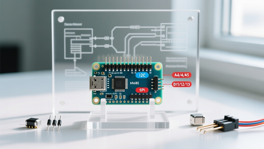
- SPI Bus (10, 11, 12, 13): Used for high-speed communication with SD cards, RFID readers, and TFT displays. Pin 13 also routes to the onboard diagnostic LED.
- I2C Bus (A4, A5): Dedicated SDA (A4) and SCL (A5) lines for sensors and OLED screens. Duplicated on the separate 6-pin header near the USB port.
The R3 vs. R4 Pinout Divergence
If you are using the newer Uno R4 Minima, the physical layout is identical, but the Arduino R4 Minima datasheet reveals new capabilities. The R4 introduces a 12-bit DAC (Digital-to-Analog Converter) on pin A0 and an internal Op-Amp routed to A1 and A2. Furthermore, the R4 operates natively at 5V but features a VRTC pin for battery backup, which the R3 lacks entirely.
Setup Guide: Wiring Your First External Circuit
While the Uno features an onboard LED on Pin 13, relying on it teaches you nothing about circuit design. For your first project, we will wire an external 5mm red LED to Pin 8. This requires calculating a current-limiting resistor to protect the ATmega328P microcontroller from overcurrent damage.
Step 1: The Resistor Calculation
The ATmega328P GPIO pins have an absolute maximum current rating of 40mA, but the recommended safe continuous operating current is 20mA per pin, with a total package limit of 200mA for all VCC/GND pins combined.
Let us target a safe 15mA for our standard red LED.
- Source Voltage (V_s): 5.0V (from Uno digital pin HIGH)
- LED Forward Voltage (V_f): ~2.1V (typical for standard red 5mm LEDs)
- Target Current (I): 0.015A (15mA)
Using Ohm’s Law: R = (V_s - V_f) / I
R = (5.0 - 2.1) / 0.015 = 193.3 Ohms
The closest standard E12 resistor value is 220Ω. Using a 220Ω resistor yields a safe current of ~13.1mA.
Step 2: Breadboard Wiring
- Insert the Arduino Uno and a standard half-size breadboard into your workspace.
- Connect a jumper wire from the Uno GND pin to the blue negative rail on the breadboard.
- Insert the 220Ω resistor: one leg into Pin 8's row, the other leg into an empty row (e.g., Row 10).
- Insert the LED: the Anode (longer leg) into Row 10 (sharing the resistor), and the Cathode (shorter leg, flat edge) into the blue GND rail.
First Project Code: External Blink
Open the Arduino IDE (version 2.3+ recommended for 2026 workflows). Navigate to Tools > Board and select your specific Uno model. Paste the following code, which includes a non-blocking structure using millis() instead of the beginner delay() function, allowing you to add more tasks later without freezing the processor.
// Pin assignment based on physical wiring
const int LED_PIN = 8;

// Timing variables
unsigned long previousMillis = 0;
const long interval = 1000; // 1000ms = 1 second
int ledState = LOW;

void setup() {
  // Initialize digital pin 8 as an output
  pinMode(LED_PIN, OUTPUT);

  // Optional: Initialize serial for debugging
  Serial.begin(9600);
  Serial.println("External LED Blink Initialized.");
}

void loop() {
  unsigned long currentMillis = millis();

  // Check if it's time to toggle the LED
  if (currentMillis - previousMillis >= interval) {
    previousMillis = currentMillis; // Save the last toggle time

    // Toggle state
    ledState = (ledState == LOW) ? HIGH : LOW;
    digitalWrite(LED_PIN, ledState);
  }

  // You can add other non-blocking code here
}
Critical Failure Modes: How Beginners Fry Their Boards
Even with the correct Arduino Uno pin diagram in hand, hardware damage usually stems from three specific oversights. Avoid these to ensure your board survives past the prototyping phase.
1. Backfeeding Voltage via the 5V Pin
If you power an external circuit via a bench supply and connect its 5V output to the Uno’s 5V pin while the USB cable is also plugged in, you create a ground loop and voltage conflict. The USB 5V rail and your external supply will fight each other, potentially backfeeding into your computer’s USB controller or blowing the Uno’s resettable polyfuse. Rule: Only use the 5V pin as an output when on USB, or as an input when USB is strictly disconnected.
2. Missing the Common Ground
When interfacing the Uno with external modules (like a 12V relay board or a separate motor driver), beginners often connect the signal wire but forget the ground wire. Without a shared GND reference between the Uno and the external power supply, the 5V logic signal will float, causing erratic behavior, random reboots, or sending current backward through the microcontroller’s ESD protection diodes, permanently destroying the GPIO pin.
3. Exceeding the 3.3V Regulator Limit
Modern sensors (like the BME280 or ESP-01 modules) often require 3.3V. The Uno R3’s onboard 3.3V regulator is a simple linear drop-down capable of supplying a maximum of 150mA. Attempting to power an ESP8266 WiFi module (which spikes to 300mA+ during transmission) directly from the Uno’s 3.3V pin will cause the voltage to brown out, resetting the microcontroller and potentially damaging the regulator silicon over time. Always use an external buck converter for high-draw 3.3V peripherals.
Next Steps and Expansion
Now that you have mastered the physical Arduino Uno pin diagram and safely driven an external load, your next step is to read analog inputs. Try wiring a 10kΩ potentiometer to the A0 pin, using the analogRead() function to map the 0-1023 integer range to the PWM analogWrite() function on Pin 9, giving you physical dimming control over your external LED.