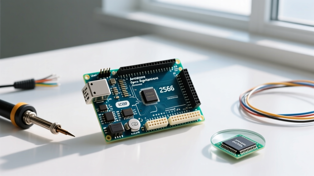

Introduction to the Arduino Mega 2560
When your project outgrows the humble Arduino Uno, the Arduino Mega 2560 is the traditional next step. Designed for complex applications requiring extensive I/O, multiple serial connections, and larger memory footprints, the Mega 2560 remains a staple in robotics, 3D printing (like RAMPS setups), and home automation. As of 2026, a genuine Arduino Mega 2560 Rev3 retails for approximately $49.00, while reliable third-party clones from brands like Elegoo or HiLetgo are widely available for $14.00 to $18.00. Understanding the exact Arduino Mega 2560 specs is critical before designing your PCB or writing your first sketch. This beginner guide breaks down the microcontroller architecture, pinout capabilities, power limitations, and real-world failure modes you need to know.
Core Microcontroller and Memory Architecture
At the heart of the board is the Microchip ATmega2560, an 8-bit AVR microcontroller operating at 16 MHz. While 8-bit processors might seem dated compared to modern 32-bit ARM Cortex boards (like the Raspberry Pi Pico or Arduino Portenta), the ATmega2560 offers unmatched simplicity, 5V logic tolerance, and a massive ecosystem of legacy shields. According to the official Microchip ATmega2560 product documentation, the chip's memory is partitioned into three distinct areas, which dictates how you handle data in your C++ sketches.
| Memory Type | Capacity | Primary Use Case | Beginner Tip |
|---|---|---|---|
| Flash Memory | 256 KB (8 KB used by bootloader) | Storing compiled code and constants. | Use the PROGMEM keyword to store large string arrays here instead of SRAM. |
| SRAM | 8 KB | Dynamic variables, arrays, and runtime data. | 8 KB fills up fast. Avoid massive local arrays; use global scope or external EEPROM. |
| EEPROM | 4 KB | Persistent data storage across power cycles. | Use for saving calibration data or user settings. Limited to ~100,000 write cycles. |
Pinout Breakdown and I/O Capabilities
The most defining Arduino Mega 2560 spec is its massive I/O count. The board exposes 54 digital I/O pins and 16 analog input pins. Here is how those pins are distributed and what you need to watch out for:
Digital I/O and PWM
- 54 Digital Pins (D0 - D53): All can be configured as inputs or outputs using
pinMode(). - 15 PWM Pins (D2 - D13, D44 - D46): These provide 8-bit PWM output (0-255) via
analogWrite(). By default, the PWM frequency is 490 Hz. However, pins 4 and 13 operate at 980 Hz. This is a crucial detail if you are driving audio circuits or specific motor controllers that require higher base frequencies. - Current Limits: The absolute maximum DC current per I/O pin is 40 mA, but Microchip strongly recommends keeping continuous draw under 20 mA to prevent silicon degradation. Always use a transistor or MOSFET to drive loads like solenoids or high-power LEDs.
Analog Inputs
The Mega features 16 analog inputs (A0 - A15), each providing 10-bit resolution (0-1023 integer values mapping to 0V - 5V). Unlike the Uno, which shares analog pins with digital I/O, the Mega dedicates a separate header row exclusively for analog inputs, leaving the digital headers completely free for other uses.
Communication Protocols
Pro-Tip: The Mega's 4 hardware serial ports are its biggest advantage for multi-sensor projects. You can debug via the USB Serial port while simultaneously talking to a GPS module, a cellular modem, and an RFID reader without relying on slow, CPU-blocking software serial libraries.
- Hardware Serial (UART): 4 ports (Serial, Serial1, Serial2, Serial3). Pins 0/1, 19/18, 17/16, and 15/14 respectively.
- I2C (TWI): Pins 20 (SDA) and 21 (SCL). Note that the Mega also includes a dedicated 4-pin I2C header near the USB port, which is wired in parallel to pins 20/21 for easier shield stacking.
- SPI: Pins 50 (MISO), 51 (MOSI), 52 (SCK), and 53 (SS). Unlike the Uno, the SPI pins on the Mega are not on pins 11-13. They are located on the 6-pin ICSP header and the extended digital header. This breaks compatibility with older Uno shields that hardcode SPI to pins 11-13.
Power Requirements and Real-World Limits
Powering the Mega 2560 incorrectly is the fastest way to destroy the board. According to the Arduino Official Mega 2560 Documentation, the board can be powered via the USB connection (5V) or the external power jack (VIN).
Voltage Regulator Thermal Limits
The onboard AMS1117-5.0 linear voltage regulator steps down the VIN voltage to 5V. The recommended input voltage is 7V to 12V. If you supply 12V to the barrel jack and draw 500 mA from the 5V pin, the regulator must dissipate (12V - 5V) * 0.5A = 3.5 Watts of heat. The AMS1117 in a SOT-223 package lacks a heatsink and will trigger thermal shutdown around 150°C, which it will hit rapidly at this dissipation level. Rule of thumb: If your 5V load exceeds 200 mA, bypass the onboard regulator and supply regulated 5V directly to the 5V pin (with USB disconnected).
The 3.3V Pin Limit
Beginners often mistakenly assume the 3.3V pin can supply the same current as the 5V pin. The Mega's 3.3V output is generated by a secondary LDO (often an LP2985) which is strictly limited to 150 mA. Attempting to power a modern ESP32 or a high-brightness TFT display directly from the Mega's 3.3V pin will cause brownouts and system resets.
Arduino Mega 2560 vs. Uno R3/R4 Comparison
To contextualize the Mega's specs, here is how it stacks up against the standard Uno form factor in 2026.
| Feature | Arduino Uno R3 | Arduino Uno R4 Minima | Arduino Mega 2560 |
|---|---|---|---|
| Microcontroller | ATmega328P (8-bit) | RA4M1 (32-bit ARM) | ATmega2560 (8-bit) |
| Operating Voltage | 5V | 5V | 5V |
| Flash Memory | 32 KB | 256 KB | 256 KB |
| SRAM | 2 KB | 32 KB | 8 KB |
| Digital I/O Pins | 14 | 14 | 54 |
| PWM Pins | 6 | 6 | 15 |
| Hardware Serial Ports | 1 | 1 | 4 |
| Approx. Price (2026) | $27.00 | $20.00 | $49.00 |
Common Failure Modes and Troubleshooting
Even with careful handling, beginners frequently encounter specific hardware issues with the Mega 2560. Recognizing these failure modes will save you hours of debugging.
1. USB-to-Serial Firmware Corruption
The Mega uses a dedicated ATmega16U2 chip to handle USB-to-Serial conversion. If you accidentally short the 5V pin to GND while the board is plugged into USB, you can blow the 16U2's internal voltage regulator or corrupt its firmware. Symptom: The board powers on, but the PC does not recognize the USB device, or it shows up as an unknown device. Fix: You can reflash the 16U2 firmware using an external ISP programmer via the 6-pin ICSP header nearest to the USB port.
2. The 'Pilot LED' Short Circuit
On many cheap clone boards, the buffer resistor for the onboard 'L' LED (pin 13) is poorly soldered or missing. If you connect a heavy load directly to Pin 13 without an external current-limiting resistor, you may backfeed current through the LED circuit, damaging the ATmega2560's PORTB output driver.
3. I2C Bus Lockups
Because the Mega operates at 5V logic, connecting 3.3V I2C sensors (like the BME280 or modern OLEDs) directly to pins 20 and 21 without a logic level shifter can result in bus lockups or, over time, fry the sensor's internal pull-up resistors. Always use a bidirectional logic level converter (like the Texas Instruments TXS0108E or standard N-channel MOSFET shifters) when mixing 5V and 3.3V I2C devices.
Final Verdict: When to Choose the Mega
The Arduino Mega 2560 specs make it the undisputed king of 5V legacy compatibility and high-pin-count projects. If you are building a CNC router, a multi-zone greenhouse controller, or a complex robotics chassis requiring 4+ UART devices, the Mega is the correct choice. However, if your project requires heavy floating-point math, high-speed audio processing, or native Wi-Fi/Bluetooth, you should look toward 32-bit alternatives like the ESP32 or Raspberry Pi Pico, using the Mega strictly as an I/O expander via I2C or Serial. For pure, rugged, high-I/O 8-bit control, the Mega 2560 remains an indispensable tool in the maker's arsenal.