
The Evolution of "Arduino Nano Wi-Fi" Projects
For years, the search term Arduino Nano Wi-Fi brought up a patchwork of frustrating hacks. Makers would wire an ESP-01S module to a classic ATmega328P Nano via UART, battling AT-command firmware, baud-rate mismatches, and 5V-to-3.3V logic level shifting nightmares. While that method still exists, the landscape of microcontrollers has fundamentally shifted.
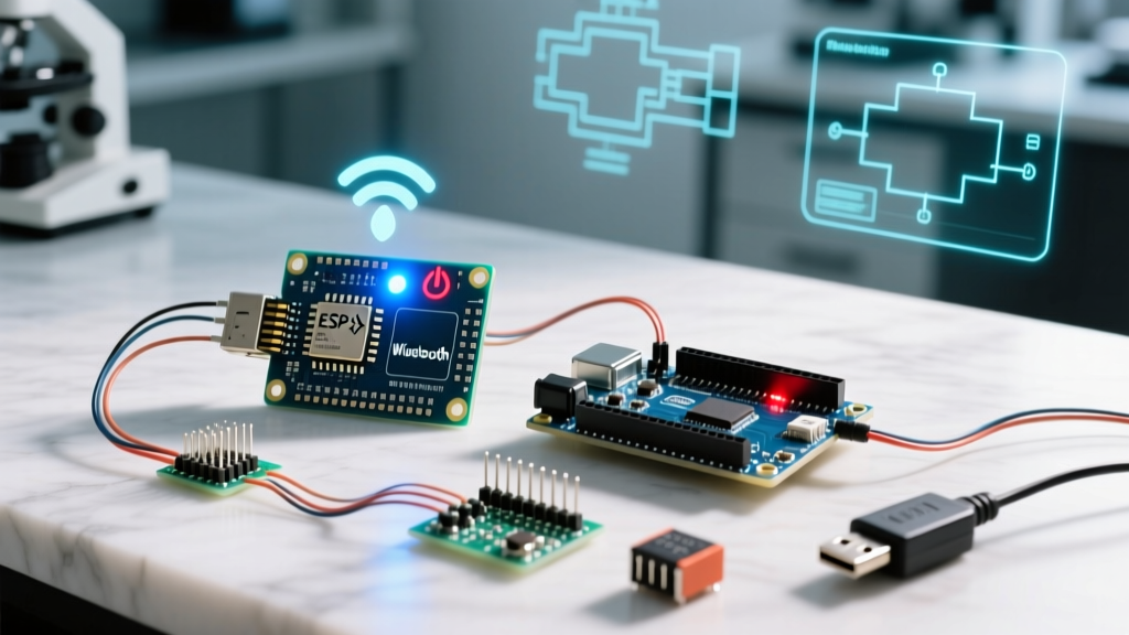
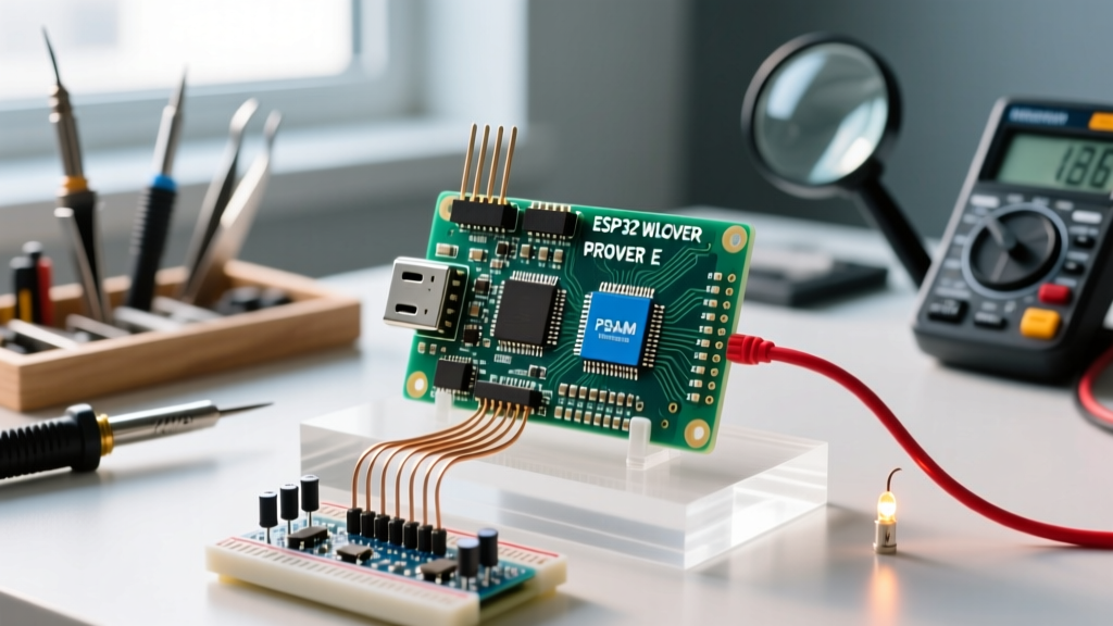
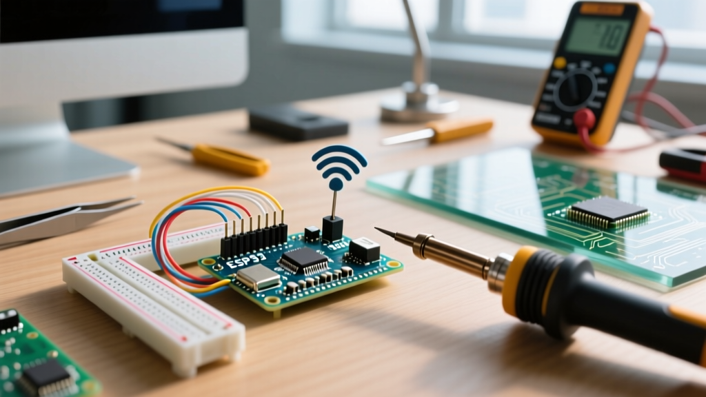
Today, the definitive solution for an Arduino Nano form factor with native wireless capabilities is the Arduino Nano ESP32. Priced around $21.50, it retains the exact 18-pin footprint of the classic Nano but swaps the aging ATmega328P for a dual-core ESP32-S3, complete with native Wi-Fi and Bluetooth 5.0. No co-processors, no AT commands, and no external voltage dividers required.
In this setup and first-project tutorial, we will build a Wi-Fi-enabled environmental sensor node that reads temperature and humidity data and pushes it to a local server via HTTP GET requests.
Platform Comparison: Classic Hack vs. Modern Native
Before diving into the wiring, it is crucial to understand why upgrading your approach to the Nano ESP32 saves hours of debugging. Below is a technical comparison of the legacy method versus the modern native approach.
| Feature | Classic Nano + ESP-01S (Legacy) | Arduino Nano ESP32 (Modern) |
|---|---|---|
| Core MCU | ATmega328P (8-bit, 16MHz) | ESP32-S3 (Dual-core, 240MHz) |
| Wi-Fi Implementation | External UART Co-processor | Native 2.4GHz 802.11 b/g/n |
| Logic Levels | 5V (Requires level shifter for ESP RX) | Native 3.3V (Direct I2C/SPI compatibility) |
| Code Complexity | High (AT strings, serial buffer parsing) | Low (Standard Arduino WiFi.h API) |
| Approx. Cost (2026) | $6.50 (Clone Nano + ESP-01S) | $21.50 (Official Arduino) |
Hardware Bill of Materials (BOM)
To build this IoT sensor node, gather the following components:
- Microcontroller: Arduino Nano ESP32 (Official or high-quality clone with ESP32-S3).
- Sensor: BME280 Breakout Board (I2C version). Avoid the cheaper DHT11/DHT22 sensors for production IoT nodes; the Bosch BME280 offers vastly superior accuracy and I2C bus stability.
- Power: High-quality USB-C data cable (capable of 5V/1A+). Do not use cheap charge-only cables.
- Wiring: 4x Male-to-Male jumper wires.
Step 1: Arduino IDE Environment Setup
The Nano ESP32 is fully supported in Arduino IDE 2.x. Follow these precise steps to configure your compiler environment:
- Open Arduino IDE and navigate to File > Preferences.
- In the "Additional boards manager URLs" field, ensure the official Arduino ESP32 core URL is present. (Usually handled natively in IDE 2.3+, but verify the Espressif core is installed).
- Open the Boards Manager (left sidebar icon) and search for
Arduino ESP32 Boards. Install the latest version. - Connect your Nano ESP32 via USB-C. In the IDE, select Tools > Board > Arduino ESP32 Boards > Arduino Nano ESP32.
- Under Tools > USB Mode, select Hardware CDC and JTAG. This ensures stable serial monitoring and debugging capabilities.
Step 2: Wiring the BME280 Sensor
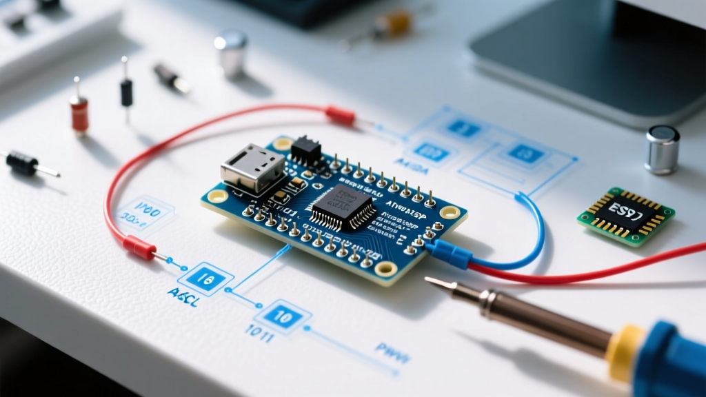
The ESP32-S3 operates strictly at 3.3V logic. Fortunately, modern BME280 breakouts include onboard voltage regulators and logic level shifters, allowing safe connection to the 3.3V rail.
I2C Pinout Mapping
- VCC on BME280 → 3.3V on Nano ESP32
- GND on BME280 → GND on Nano ESP32
- SCL on BME280 → A5 on Nano ESP32
- SDA on BME280 → A4 on Nano ESP32
Expert Warning: Never connect the BME280 VCC pin to the 5V pin on the Nano ESP32 if your specific breakout board lacks an onboard 3.3V LDO regulator. Supplying 5V directly to a raw BME280 chip will instantly destroy the sensor's internal CMOS structure.
Step 3: Writing the Wi-Fi IoT Code
We will use the native WiFi.h and HTTPClient.h libraries native to the ESP32 core, alongside the Adafruit_BME280 library (install via Library Manager). The code below connects to your router, reads the sensor, and transmits the payload to a local API endpoint.
#include <WiFi.h>
#include <HTTPClient.h>
#include <Wire.h>
#include <Adafruit_Sensor.h>
#include <Adafruit_BME280.h>

// Network Credentials
const char* ssid = "YOUR_WIFI_SSID";
const char* password = "YOUR_WIFI_PASSWORD";

// API Endpoint
const char* serverName = "http://192.168.1.100/api/sensor-data";

Adafruit_BME280 bme;
unsigned long lastTime = 0;
unsigned long timerDelay = 15000; // Send data every 15 seconds

void setup() {
  Serial.begin(115200);
  while(!Serial); // Wait for serial monitor

  // Initialize I2C on Nano ESP32 default pins (A4=SDA, A5=SCL)
  Wire.begin();

  if (!bme.begin(0x76)) {
    Serial.println("Could not find a valid BME280 sensor, check wiring!");
    while (1);
  }

  // Connect to Wi-Fi
  WiFi.begin(ssid, password);
  Serial.print("Connecting to Wi-Fi");
  int timeout = 0;
  while (WiFi.status() != WL_CONNECTED) {
    delay(500);
    Serial.print(".");
    timeout++;
    if(timeout > 40) {
      Serial.println("\nWi-Fi connection failed. Rebooting...");
      ESP.restart();
    }
  }
  Serial.println("\nConnected! IP: " + WiFi.localIP().toString());
}

void loop() {
  if ((millis() - lastTime) > timerDelay) {
    if(WiFi.status() == WL_CONNECTED) {
      HTTPClient http;

      float temp = bme.readTemperature();
      float hum = bme.readHumidity();

      // Construct JSON payload
      String payload = "{\"temperature\":" + String(temp) + ",\"humidity\":" + String(hum) + "}";

      http.begin(serverName);
      http.addHeader("Content-Type", "application/json");

      int httpResponseCode = http.POST(payload);
      Serial.printf("HTTP Response code: %d\n", httpResponseCode);

      http.end();
    } else {
      Serial.println("Wi-Fi Disconnected. Attempting reconnect...");
      WiFi.reconnect();
    }
    lastTime = millis();
  }
}
Advanced Troubleshooting & Edge Cases
Working with the ESP32-S3 in the Nano footprint introduces specific hardware quirks. If your project fails, consult these expert-level troubleshooting scenarios.
1. The "Brownout Detector Was Triggered" Error
This is the most common failure mode in ESP32 Wi-Fi projects. When the Nano ESP32 transmits a Wi-Fi packet, the radio draws a transient current spike of up to 350mA. If your USB cable has thin internal wires (e.g., 28AWG) or your PC's USB port limits current, the voltage at the board's 5V rail drops below 4.3V. The ESP32's internal brownout detector trips, resetting the board in an infinite loop.
Fix: Use a high-quality, short USB-C cable rated for data and 2A charging. Alternatively, power the board via the VIN pin with a regulated 5V/1A external power supply.
2. Antenna Selection: PCB vs. u.FL
The official Arduino Nano ESP32 features both a PCB trace antenna and a u.FL connector for an external antenna. Out of the box, the board routes the RF signal to the PCB antenna. If you are mounting the Nano inside a metal enclosure, the PCB antenna will fail to connect to Wi-Fi.
Fix: To use an external u.FL antenna, you must rework the board. According to the Espressif ESP32-S3 Technical Documentation and Arduino schematics, this involves desoldering a microscopic 0-ohm resistor and moving it to the adjacent pad to route the RF trace to the u.FL connector. If you are not comfortable with hot-air SMD rework, purchase a board variant that defaults to u.FL or design your enclosure with an RF-transparent window.
3. Recovering a "Bricked" Board (DFU Mode)
If you upload faulty code that crashes the USB stack, the Nano ESP32 may disappear from your PC's device manager. You must force it into ROM Bootloader (DFU) mode.
- Disconnect the USB-C cable.
- Use a jumper wire to short the GND pin to the B1 pin (labeled on the underside or schematic as the boot pad).
- Reconnect the USB-C cable while maintaining the short.
- Remove the jumper wire. The board will enumerate as an ESP32-S3 DFU device, allowing you to flash a known-good sketch.
Conclusion
Upgrading your "Arduino Nano Wi-Fi" workflow from legacy AT-command hacks to the native Nano ESP32 drastically reduces development time and hardware complexity. By leveraging the ESP32-S3's native I2C and Wi-Fi stacks, you can deploy robust, low-latency IoT sensor nodes that fit in the palm of your hand. Ensure you respect the 3.3V logic constraints and provide adequate transient current for the Wi-Fi radio, and your first project will run flawlessly.