
The Enduring Legacy of the Pro Mini in 2026
Despite the market dominance of the ESP32 and Raspberry Pi Pico, the Arduino Pro Mini remains an irreplaceable workhorse for ultra-low-power, battery-operated embedded projects. Stripped of the onboard USB-to-Serial converter and voltage regulators found on the Uno, it offers a raw, lightweight footprint. However, this minimalism creates a unique hurdle: the Arduino Pro Mini pin layout is notoriously sparse on silkscreen markings, making community library integration and hardware mapping a frequent stumbling block for DIYers.
When leveraging massive community-driven ecosystems like the Adafruit Sensor Library, RadioHead, or U8g2, understanding exactly how physical board traces map to software-defined pins is critical. This guide bridges the gap between the physical hardware layout and modern software library requirements, ensuring your 2026 sensor nodes and wireless meshes compile and run without hardware-level faults.
The Great I2C Clone Divide: A4/A5 vs. Dedicated Headers
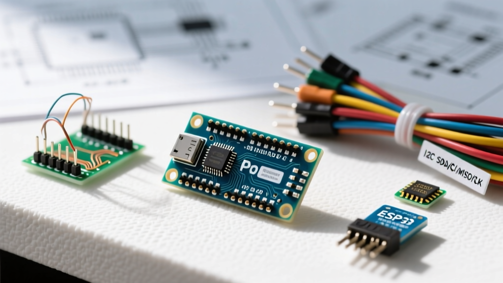
The most heavily debated topic in Pro Mini community forums revolves around I2C pinouts. The original SparkFun design routed I2C exclusively through analog pins A4 (SDA) and A5 (SCL). However, the massive influx of overseas clone boards over the last decade introduced a secondary set of dedicated SDA and SCL headers on the bottom edge of the PCB.
How the Wire Library Handles the Divide
When you call Wire.begin() in your sketch, the underlying AVR Wire library defaults to the hardware I2C pins. On a 5V/16MHz ATmega328P Pro Mini, these are physically tied to PC4 (SDA) and PC5 (SCL).
- Original & Early Clones: You must wire your OLEDs or BME280 sensors directly to the A4 and A5 headers on the right side of the board.
- Modern Clones (Post-2018): Feature duplicate SDA/SCL pins on the bottom edge. Electrically, these are wired in parallel to A4/A5. You can use either set, but the bottom edge is preferred for stacking shields or using ribbon cables.
Expert Troubleshooting: If your I2C scanner sketch returns no devices, verify your board's pull-up resistors. Many cheap Pro Mini clones omit the 4.7kΩ I2C pull-ups to save fractions of a cent. If your sensor module also lacks them, the I2C bus will float, causing Wire.endTransmission() to hang indefinitely.
Standard Community Library Pin Mapping Matrix
To eliminate guesswork, refer to this mapping matrix when configuring the most popular community libraries. This assumes a standard 5V/16MHz ATmega328P Pro Mini.
| Community Library | Target Hardware | Required Pro Mini Pins | Configuration Notes & Edge Cases |
|---|---|---|---|
| RF24 (nRF24L01) | 2.4GHz Transceiver | CE: D9, CSN: D10, MOSI: D11, MISO: D12, SCK: D13 | Requires 3.3V logic. A 5V Pro Mini will fry the nRF24L01 without a logic level shifter or a dedicated 3.3V adapter base. |
| U8g2 (OLED) | SSD1306 128x64 I2C | SDA: A4, SCL: A5 | Use the u8g2_ssd1306_128x64_noname_f_hw_i2c constructor to leverage hardware I2C and save SRAM. |
| RadioHead (ASK) | 433MHz TX/RX Modules | TX: D12, RX: D11 | Do not use D0/D1. The ASK library relies on timer interrupts; avoid using D9/D10 if utilizing PWM simultaneously. |
| OneWire (DS18B20) | Temperature Sensor | Any Digital Pin (e.g., D2) | Requires a 4.7kΩ external pull-up resistor to VCC. Pin D2 is preferred for external interrupt wake-up capabilities. |
| Adafruit_NeoPixel | WS2812B LED Strips | Any Digital Pin (e.g., D6) | Disable interrupts during show(). Avoid using hardware serial pins (D0/D1) to prevent FTDI upload conflicts. |
Serial Bottlenecks: FTDI Conflicts and Software Forks
Unlike the Arduino Uno, the Pro Mini lacks a dedicated USB-to-Serial chip. You must use an external FTDI programmer (like the FT232RL or CP2102) connected to the GND, VCC, TXI (D0), and RXO (D1) pins. This creates a massive architectural bottleneck: D0 and D1 are permanently occupied by the programming interface.
The Hardware Serial Collision
If you are integrating a community library that strictly demands Hardware Serial (such as certain NMEA GPS parsers or DFPlayer Mini MP3 modules), you will face a collision. Uploading code via the FTDI adapter will fail if the GPS module is actively transmitting data on D0/D1, as the FTDI chip cannot overpower the sensor's TX line.
The Community Solution: The AVR community heavily favors alternative software serial libraries to bypass this. While the standard SoftwareSerial.h is notorious for blocking interrupts and dropping bytes at baud rates above 38400, modern forks have solved this:
- NeoSWSerial: Highly recommended for the Pro Mini. It supports simultaneous RX/TX and works reliably at 9600, 19200, and 38400 baud without disabling global interrupts.
- AltSoftSerial: Uses hardware timers instead of pin-change interrupts. It is incredibly reliable but strictly requires the use of Pins D8 (RX) and D9 (TX) on the ATmega328P Pro Mini. This disables PWM on D9 and D10.
Direct Port Manipulation for Memory-Starved Libraries
When working with complex community libraries on the Pro Mini's limited 2KB SRAM, standard digitalWrite() functions introduce unacceptable overhead. Advanced users optimizing libraries for high-speed data logging or multiplexed LED matrices utilize direct port manipulation based on the physical ATmega328P pinout.
According to the Arduino SPI reference and AVR datasheets, the Pro Mini's digital pins map to three internal ports:
- PORTD (D0 to D7): Controls standard digital pins and hardware serial. Writing directly to
PORTDallows you to toggle 8 pins in a single clock cycle. - PORTB (D8 to D13): Contains the hardware SPI pins (MOSI, MISO, SCK) and the onboard LED (D13).
- PORTC (A0 to A5): Analog pins, which can also be used as standard digital I/O (D14 to D19).
Example: If a community library requires rapid toggling of D4, D5, D6, and D7 for a parallel LCD interface, replacing digitalWrite() with PORTD |= B11110000; reduces execution time from ~5 microseconds to ~0.125 microseconds, preventing buffer underruns in high-speed sensor libraries.
Power Pins, RAW Limits, and Logic Level Failures
The physical layout of the Pro Mini's power section is a frequent source of catastrophic failure when integrating 3.3V community sensor libraries on 5V boards. The board features three distinct power input points:
- VCC Pin: Bypasses the onboard voltage regulator. Must be exactly 5V (for 16MHz boards) or 3.3V (for 8MHz boards). Supplying 5V to a 3.3V board's VCC pin will instantly destroy the ATmega328P.
- RAW Pin: Feeds the onboard MIC5205 voltage regulator. While the regulator is technically rated up to 12V, the SparkFun Pro Mini Hookup Guide warns that the tiny SMD regulator lacks a heatsink. Inputting 12V will cause thermal shutdown when drawing more than 30mA. Best Practice: Keep RAW input between 5.5V and 9V.
- 3.3V Pin (Output only on 5V boards): On the 5V/16MHz Pro Mini, this pin is an output from the regulator's internal reference or a dedicated secondary LDO depending on the clone. It can typically only supply 5mA to 10mA—far too little to power an NRF24L01 or an SD card module.
2026 Hardware Tip: If your community library requires driving a 3.3V SPI sensor (like the BME688) from a 5V Pro Mini, do not rely on the board's 3.3V output pin for power. Use an external AMS1117-3.3 buck module fed from the RAW pin, and utilize a bidirectional logic level shifter (like the Texas Instruments TXS0108E) on the MOSI, MISO, SCK, and CS lines to prevent frying the sensor's logic gates.
Final Thoughts on Ecosystem Integration
Mastering the Arduino Pro Mini pin layout is less about memorizing numbers and more about understanding the electrical realities of the ATmega328P architecture. By respecting the I2C clone variations, utilizing modern software serial forks to avoid FTDI collisions, and leveraging direct port manipulation, you can seamlessly integrate any modern community library into your low-power builds. Always verify your specific board's voltage variant before wiring external sensor arrays, and rely on hardware-specific library constructors to preserve the Pro Mini's most valuable resource: its 2KB of SRAM.