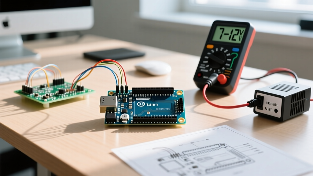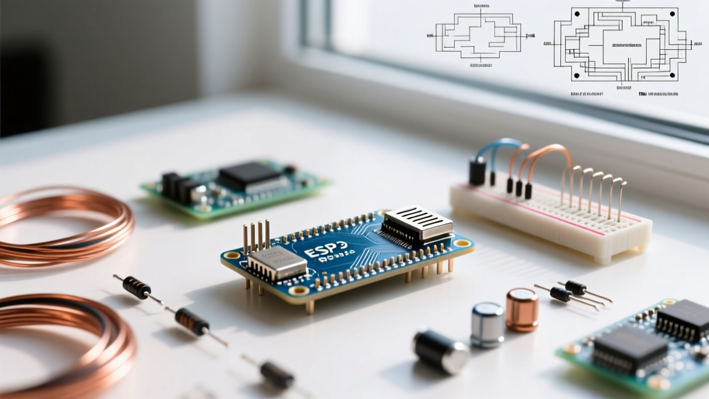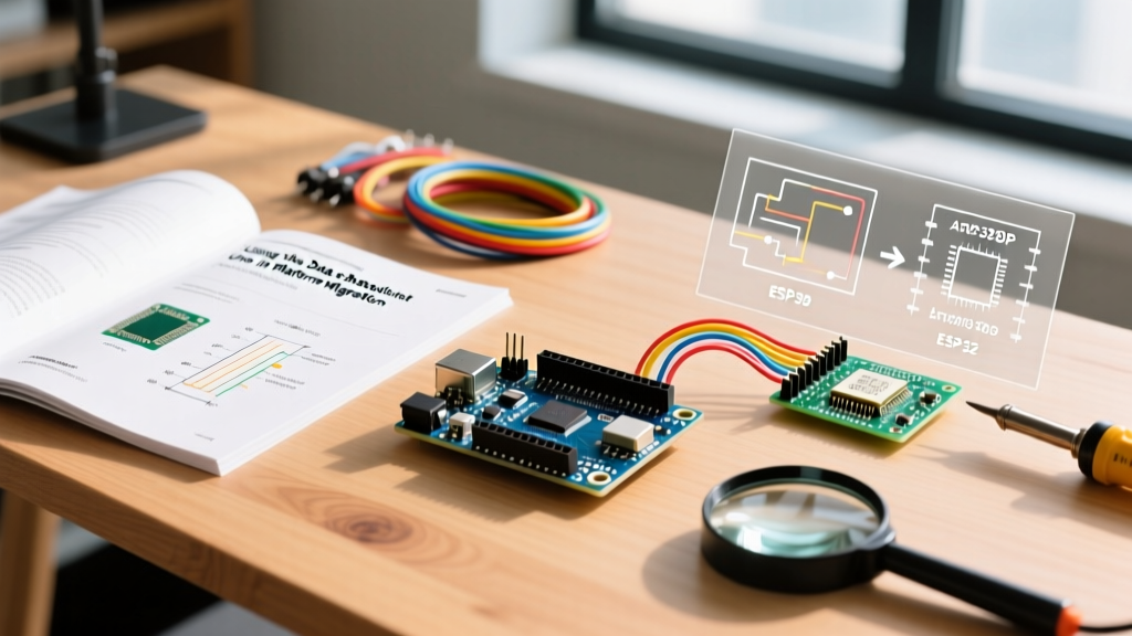

The Blueprint for Leaving the Prototyping Phase
The Arduino Uno is the undisputed champion of rapid prototyping. Its forgiving 5V logic, robust DIP footprint, and massive community support make it the default starting point for millions of embedded projects. However, when a project transitions from a breadboard concept to a commercial product or a complex IoT deployment, the Uno's physical footprint, high idle power consumption, and limited processing headroom become critical bottlenecks. This is where mastering the data sheet for Arduino Uno becomes your most valuable migration tool.
Platform migration is not simply about swapping one microcontroller for another. It requires a meticulous audit of your current hardware dependencies. By deeply analyzing the specifications of the Uno and its underlying silicon, you can map a precise, failure-free route to advanced platforms like the ESP32-S3, STM32G4 series, or a custom bare-metal PCB.
Deconstructing the 'Data Sheet for Arduino Uno'
A common point of confusion among intermediate makers is searching for a single 'Arduino Uno datasheet.' In reality, you must consult two distinct documents to fully understand the platform's capabilities and limits:
- The Board Schematic: This details the peripheral components on the Uno Rev3 PCB, including the NCP1117 5V LDO voltage regulator, the ATmega16U2 USB-to-Serial converter, and the 16MHz crystal oscillator. You can review the official Arduino Uno Rev3 Schematic to understand the board-level power and routing constraints.
- The Silicon Datasheet: This is the Microchip (formerly Atmel) ATmega328P datasheet. It defines the core architecture, register maps, timing diagrams, and electrical characteristics of the brain itself. The Microchip ATmega328P Product Page provides access to the full 660-page technical document.
Expert Insight: Never assume the capabilities of the Uno board match the ATmega328P chip exactly. The board's onboard components—like the USB interface and power LEDs—drastically alter the power profile and available I/O pins compared to the bare silicon.
The Migration Matrix: ATmega328P vs. Modern Alternatives
When planning your migration, you must compare the hard limits of the Uno's architecture against your target platform. Below is a technical comparison matrix highlighting the critical deltas when moving from the Uno to popular production alternatives.
| Specification | Arduino Uno (ATmega328P) | ESP32-S3-WROOM-1 | STM32G431CBU6 |
|---|---|---|---|
| Core Architecture | 8-bit AVR | 32-bit Xtensa LX7 (Dual) | 32-bit ARM Cortex-M4F |
| Clock Speed | 16 MHz (External) | 240 MHz | 170 MHz |
| Logic Level | 5V (TTL) | 3.3V | 3.3V (5V tolerant I/O) |
| ADC Resolution | 10-bit (6 channels) | 12-bit (20 channels) | 12-bit (up to 5 ADC instances) |
| Hardware I2C/SPI | 1x I2C / 1x SPI | 2x I2C / 4x SPI | 3x I2C / 3x SPI |
| Active Current | ~12 mA (Bare chip at 16MHz) | ~25 mA (Wi-Fi off, CPU active) | ~15 mA (CPU active, no RF) |
| Approx. Unit Cost (1k qty) | $2.90 (DIP-28) | $2.10 (Module) | $3.40 (QFN-48) |
Power Consumption: The Hidden Board-Level Penalties
One of the primary reasons engineers migrate away from the Uno is power inefficiency in battery-operated deployments. If your prototype draws 45mA while 'sleeping,' the culprit is the Uno board, not necessarily your code.
Auditing the Uno Rev3 Power Tree
According to the board schematic, the Uno Rev3 features several always-on current sinks:
- NCP1117 5V LDO: Draws approximately 5mA of quiescent current, even when the main microcontroller is powered down.
- ATmega16U2 USB Controller: Consumes roughly 15mA to maintain the USB-to-Serial bridge.
- ON LED and TX/RX LEDs: Add another 5mA to 10mA depending on resistor tolerances.
To achieve true low-power operation, migrating to a bare ATmega328P or an ESP32-S3 is mandatory. The ATmega328P supports a 'Power-down' sleep mode where the current drops to 0.1µA at 1.8V, provided you disable the Brown-out Detector (BOD) via the PRR and MCUCR registers. Conversely, the ESP32-S3 Datasheet outlines a deep sleep current of roughly 7µA, which includes the ULP (Ultra-Low Power) co-processor and RTC memory retention.
Analog Constraints: The 10kΩ Impedance Rule
A frequent failure mode during platform migration involves analog sensor readings. The ATmega328P features a 10-bit Successive Approximation Register (SAR) ADC. The datasheet explicitly states that the recommended maximum source impedance for analog signals is 10kΩ.
Why? The internal sample-and-hold (S/H) capacitor is approximately 14pF. The ADC requires a maximum of 1.5 ADC clock cycles to charge this capacitor to the correct voltage level. If your voltage divider or sensor output impedance exceeds 10kΩ, the capacitor will not fully charge, resulting in non-linear, lower-than-expected readings.
Migration Action Item: When moving to an STM32 or ESP32, which often feature higher-resolution 12-bit or 16-bit ADCs, the internal sampling capacitors may be larger or the sampling windows shorter. You must recalculate your source impedance and potentially add an external op-amp buffer or an RC low-pass filter (e.g., 100Ω resistor + 100nF capacitor) to the ADC input pin to guarantee signal integrity.
Step-by-Step Migration Workflow
Follow this structured workflow to transition from the Uno prototype to your target production architecture:
- I/O and Peripheral Audit: Map every Uno pin used in your prototype to the ATmega328P's alternate functions (e.g., Timer1 for PWM, INT0/INT1 for hardware interrupts). Cross-reference these with your target MCU's pinmux capabilities.
- Logic Level Translation Strategy: The Uno operates at 5V. Modern MCUs (ESP32, STM32) operate at 3.3V. Identify all 5V sensors and actuators. For high-speed SPI/UART, avoid capacitive bidirectional shifters like the TXS0108E; instead, use dedicated directional level shifters (like the 74LVC245) or SN74LV1T34 single-bit translators to prevent signal degradation and timing skew.
- Timing and Baud Rate Recalculation: The Uno uses a 16.000 MHz crystal, yielding exact baud rates for standard UART (e.g., 9600, 115200). If your target MCU uses an internal RC oscillator (e.g., 8MHz or 48MHz), you must calculate the UART baud rate error. An error exceeding ±2% will cause framing errors in high-noise environments.
- Bare-Metal Prototyping: Before designing a custom PCB, remove the ATmega328P from the Uno socket and wire it on a breadboard with a minimal 3.3V LDO (like the MCP1700) and a 100nF decoupling capacitor on the VCC pin. Validate your firmware on the bare silicon.
Real-World Failure Modes When Ignoring the Datasheet
Skipping the granular details of the ATmega328P datasheet during migration leads to specific, hard-to-debug hardware failures:
- The Floating RESET Pin: The Uno board features a 10kΩ pull-up resistor on the RESET line. When migrating to a bare ATmega328P, failing to add this external pull-up (or failing to disable the internal reset via fuses) will cause the chip to reboot randomly due to EMI noise coupling into the high-impedance pin.
- Brown-Out Detector (BOD) Traps: The Uno ships with the BOD configured to trigger at 2.7V. If you migrate to a 2xAA battery setup (nominally 3.0V, dropping to 2.0V), the BOD will trap the microcontroller in a continuous reset loop before the batteries are fully depleted. You must use an AVR ISP programmer to lower the BOD threshold to 1.8V or disable it entirely in software before sleep.
- EEPROM Wear-Out: The ATmega328P EEPROM is rated for 100,000 write cycles. If your prototype logged data every second, it would destroy the EEPROM in just over a day. When migrating to an ESP32 or STM32, remember that these chips lack internal EEPROM and require an external I2C FRAM (like the Cypress CY15B104QN) or careful wear-leveling on external SPI Flash.
Conclusion
The Arduino Uno is a launchpad, not a final destination. By treating the data sheet for Arduino Uno—both the board schematic and the ATmega328P silicon manual—as a migration roadmap rather than just a reference manual, you eliminate the guesswork from hardware scaling. Understanding the exact impedance limits, power tree penalties, and timing constraints of your prototype ensures that your transition to an ESP32, STM32, or custom ASIC is driven by engineering precision, not trial and error.