
Understanding the Arduino Nano Power Supply Architecture
When prototyping embedded systems, power management is the silent killer of otherwise perfect circuits. The Arduino Nano remains a staple on workbenches in 2026, favored for its breadboard-friendly footprint and robust ATmega328P (or ATmega4809) ecosystem. However, its compact size obscures a complex internal power routing architecture. Misunderstanding the arduino nano power supply pathways—specifically the Vin, 5V, and 3.3V pins—is the leading cause of thermal throttling, brownouts, and fried voltage regulators in DIY robotics and IoT projects.
Whether you are using an official Arduino Nano (typically $22–$25), a third-party clone ($3–$6), or the newer Nano Every, you must understand how current flows from your source to the microcontroller's VCC rail. This deep dive dissects the board's power topology, thermal limits, and real-world failure modes.
The Three Primary Input Paths
The Nano offers three distinct methods to inject power into the system. Each path engages different protection circuits and regulation stages.
- USB Interface (Mini-USB or Micro-USB): Power enters through a 500mA resettable PTC fuse, then passes through a Schottky diode (or MOSFET ideal diode on newer revisions) to the 5V rail. This is the safest method for bench testing.
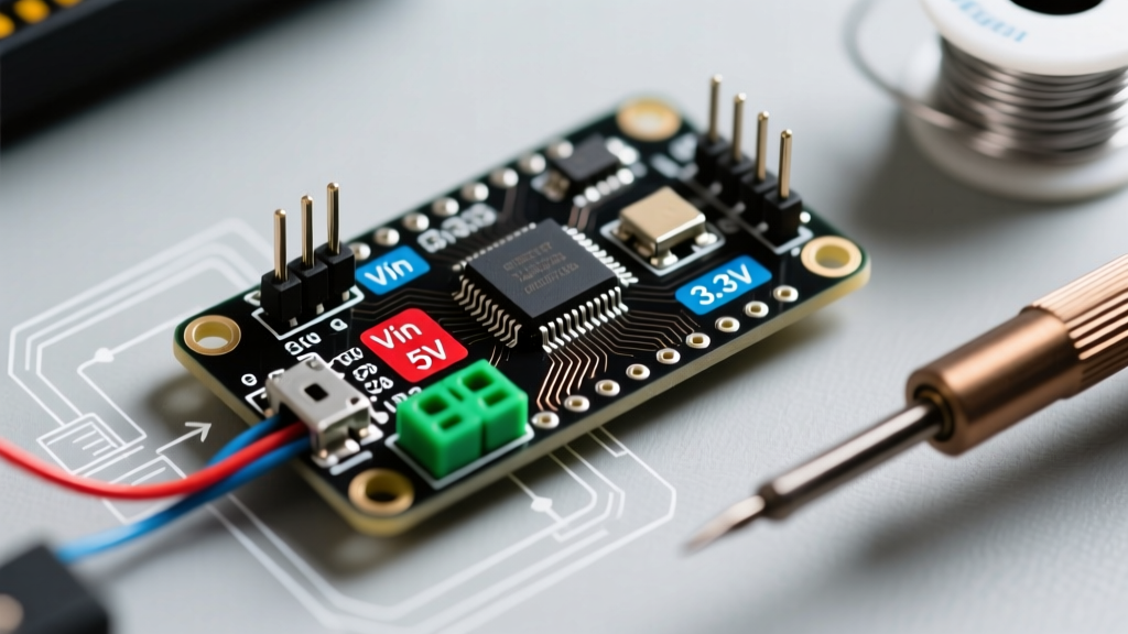
- Vin (Raw Voltage) Pin: Accepts unregulated DC voltage (recommended 7V–12V). This route forces current through the on-board linear voltage regulator before reaching the 5V rail.
- 5V Pin (Regulated Bypass): Injects power directly onto the 5V rail, entirely bypassing the on-board regulator and the USB protection diode.
Vin Pin and the On-Board Linear Regulator: Thermal Math
The most misunderstood aspect of the Nano is the Vin pin. Many beginners assume they can connect a 12V battery to Vin and draw 500mA for external sensors. This is a critical error. The classic Nano utilizes a linear regulator (often an AMS1117-5.0 or equivalent SOT-223 package) to step down the Vin voltage to 5V.
Linear regulators dissipate excess voltage as heat. The power dissipated (P) is calculated as:
P = (Vin - Vout) × Iload
If you supply 12V to Vin and draw 200mA from the 5V rail, the regulator must dissipate (12V - 5V) × 0.2A = 1.4 Watts. The SOT-223 package has a junction-to-ambient thermal resistance of approximately 50°C/W. A 1.4W dissipation results in a 70°C temperature rise above ambient. In a 25°C room, the regulator junction will hit 95°C, approaching the thermal shutdown threshold (typically 150°C, but performance degrades heavily past 100°C).
Vin Current Limits vs. Input Voltage
| Vin Input Voltage | Max Safe Continuous Current (5V Rail) | Regulator Heat Dissipation | Recommended Use Case |
|---|---|---|---|
| 7.0V (Dropout limit) | ~400 mA | 0.8W (Warm) | 3x Li-Ion cells (2S+1) or 6V Lead-Acid |
| 9.0V | ~250 mA | 1.0W (Hot) | 9V Alkaline battery (short duty cycles) |
| 12.0V | ~100 mA | 0.7W (Very Hot) | Automotive (with filtering) or 12V wall adapter |
| 15.0V+ (Absolute Max) | < 50 mA | >0.5W | Not recommended; high risk of thermal shutdown |
Note: The regulator also requires a dropout voltage of roughly 1.1V to 1.3V. Therefore, a 6V input to Vin will only yield ~4.7V on the 5V rail, causing brownouts on the ATmega328P microcontroller during high-current operations like EEPROM writes.
The 5V Pin: Bypassing the Regulator Safely
If your project requires more than 200mA at 5V (e.g., driving addressable LED strips or multiple I2C sensors), you must bypass the on-board regulator by injecting a clean, regulated 5V source directly into the 5V pin.
Critical Warning: The classic Arduino Nano lacks an auto-switching IC between the USB 5V and the 5V pin. If you connect a regulated 5V supply to the 5V pin while simultaneously connected to a PC via USB, the two 5V sources will fight each other. This can backfeed current into your PC's USB port or destroy the Nano's Schottky protection diode. Always disconnect the USB cable when injecting external power into the 5V pin, or use a USB isolator.
The 3.3V Pin Trap: FT232RL vs. CH340G vs. Nano Every
The 3.3V pin on the Nano is notoriously weak, yet it is frequently used to power ESP8266 WiFi modules or 3.3V logic sensors. The current capacity of this pin depends entirely on the USB-to-Serial chip used on your specific board variant.
- Official Classic Nano (FTDI FT232RL): The 3.3V is derived from an internal LDO inside the FT232RL chip. It is strictly limited to 50mA. Attempting to power an ESP-01 module from this pin will cause immediate voltage sag and serial communication corruption.
- Clone Nanos (WCH CH340G): The CH340G does not have an internal 3.3V LDO. Clone manufacturers often route the 3.3V pin directly to the 5V rail (a dangerous design flaw) or use a cheap, unmarked SOT-23 LDO that may supply up to 150mA, but with poor transient response.
- Arduino Nano Every (ATmega4809): The Every utilizes a dedicated, robust 3.3V LDO on the main board, capable of sourcing significantly more current, making it vastly superior for modern 3.3V sensor ecosystems.
Step-by-Step: Designing a Safe Power Tree for Robotics
Let's apply this knowledge to a common 2026 project: an Arduino Nano controlling two SG90 micro servos, an HC-SR04 ultrasonic sensor, and an I2C OLED display. The total 5V current draw peaks at roughly 650mA when both servos stall.
- Do NOT use the Vin pin. A standard 9V battery cannot supply 650mA, and the linear regulator will instantly thermally throttle.
- Do NOT use the USB port. A standard PC USB 2.0 port is limited to 500mA. The servos will cause a brownout, resetting the Nano mid-cycle.
- Implement a dedicated BEC (Battery Eliminator Circuit). Use a 2S LiPo battery (7.4V nominal) connected to a switching buck converter (like an LM2596 module or a dedicated 5V 3A UBEC).
- Wire the UBEC to the 5V Pin. Connect the UBEC's 5V output directly to the Nano's 5V pin and the ground to GND. This completely bypasses the Nano's fragile linear regulator.
- Power the 3.3V sensors separately. If using a 3.3V I2C sensor, add a secondary low-dropout regulator (like an MCP1700-330) tied to the 5V pin, rather than relying on the Nano's 3.3V pin.
Summary of Best Practices
Mastering the arduino nano power supply requires respecting the physical limits of linear regulation and USB topology. Reserve the Vin pin exclusively for low-current, high-voltage inputs (under 150mA). For any project involving motors, servos, or wireless communication modules, always use an external switching regulator tied directly to the 5V pin. Finally, verify the USB-to-Serial chip on your specific board before trusting the 3.3V rail with sensitive logic components. By designing intentional power trees, you eliminate the vast majority of erratic microcontroller behavior and ensure long-term project reliability.