
The ATmega32U4 Advantage: Native USB Architecture
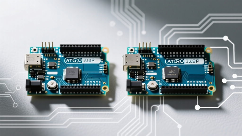
When designing compact human interface devices (HID) or space-constrained MIDI controllers, the pinout Arduino Micro offers a distinct architectural advantage over standard ATmega328P boards like the Uno. The Micro is built around the Microchip ATmega32U4 microcontroller, which features native USB communication capabilities. This eliminates the need for a secondary USB-to-Serial converter chip (like the ATmega16U2 found on the Uno), reducing board footprint, power consumption, and overall BOM cost for custom PCB integrations.
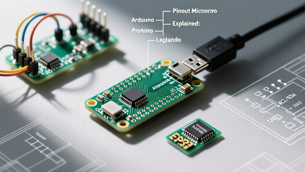
In this comprehensive board review and comparison, we dissect the exact pin mapping of the Arduino Micro, highlight critical hardware quirks you won't find in basic tutorials, and compare it against its closest siblings: the Arduino Leonardo and the SparkFun Pro Micro. Whether you are prototyping a macro keyboard or wiring up an I2C sensor array, understanding these nuances is critical for avoiding silicon-level bottlenecks in 2026.
Complete Pinout Arduino Micro Breakdown
The official Arduino Micro exposes 20 digital I/O pins (of which 7 can be used as PWM outputs and 12 as analog inputs). However, the physical silkscreen labels do not always map 1:1 with the internal ATmega32U4 port registers. Below is the definitive mapping table for advanced firmware development and direct port manipulation.
| Arduino Pin | ATmega32U4 Port | Special Functions | Notes & Edge Cases |
|---|---|---|---|
| D0 / RX | PD2 | Hardware UART (Serial1) | Do not confuse with USB CDC Serial. |
| D1 / TX | PD3 | Hardware UART (Serial1) | Used for external serial modules (GPS, BT). |
| D2 | PD1 | I2C SDA, INT1 | Crucial: I2C Data is on D2, not A4. |
| D3 | PD0 | I2C SCL, INT0, PWM | I2C Clock is on D3. Requires external pull-ups. |
| D4 - D8 | PD4, PC6, PD7, PE6, PB4 | Digital I/O | Standard digital pins, no hardware interrupts. |
| D9 - D11 | PB5, PB6, PB7 | PWM, Timer1/Timer0 | High-frequency PWM capable for motor control. |
| D13 | PC7 | Built-in LED, PWM | Shares line with onboard status LED. |
| A0 - A5 | PF7 - PF0 | Analog In, Digital 18-23 | Can be used as standard digital I/O. |
| A6 - A11 | ADC4 - ADC11 | Analog In ONLY | Cannot be used as digital I/O (ADC multiplexer). |
Board Comparison: Micro vs Pro Micro vs Leonardo
While all three boards utilize the ATmega32U4, their form factors, voltage regulation, and target use cases diverge significantly. As of 2026, supply chain stabilizations have normalized pricing, but clone markets still offer aggressive alternatives.
| Feature | Arduino Micro (Official) | SparkFun Pro Micro (5V/16MHz) | Arduino Leonardo |
|---|---|---|---|
| Form Factor | 48 x 18 mm (Breadboard friendly) | 33 x 18 mm (Ultra-compact) | 68.6 x 53.3 mm (Standard Uno shield) |
| Typical Price (2026) | ~$26.00 | ~$18.50 | ~$28.00 |
| Voltage Regulator | Onboard 5V (up to 1A input) | Onboard 5V (limited thermal mass) | Onboard 5V (Standard barrel jack input) |
| USB Connector | Micro-B | Micro-B (USB-C on newer revisions) | Micro-B |
| Best Use Case | Desktop HID, MIDI, Prototyping | Wearables, Drones, Custom PCBs | Shields, Educational Kits, Robotics |
According to the Arduino Micro Official Documentation, the Micro is designed to sit perfectly on a standard solderless breadboard, leaving one row of holes free on either side for jumper wires. The Pro Micro sacrifices this breadboard convenience for raw spatial efficiency, making it the undisputed king of custom mechanical keyboard builds and FPV drone telemetry modules. For a deeper dive into the Pro Micro's specific wiring constraints, the SparkFun Pro Micro Hookup Guide remains an invaluable resource.
Expert Wiring Scenarios & Hardware Quirks
Transitioning from an Uno to the Micro introduces several hardware traps that routinely stall intermediate makers. Here is how to navigate them.
The I2C Pin Mapping Trap
On the ATmega328P (Uno/Nano), I2C is hardwired to A4 (SDA) and A5 (SCL). On the ATmega32U4 (Micro/Leonardo), the I2C bus is routed to Digital Pin 2 (SDA) and Digital Pin 3 (SCL). If you wire an OLED display or BME280 sensor to A4/A5 on the Micro, your I2C scanner will return zero devices. Always use the Wire.h library defaults or explicitly route to D2/D3.
Power Delivery & The VUSB Limit
The Micro features a VUSB pin that routes the 5V directly from the USB host. However, standard USB 2.0 ports are limited to 500mA. If your project includes NeoPixel rings or high-draw servos, bypassing the onboard regulator via the RAW pin is safer, provided you supply a regulated 5V-7V source. Pushing more than 800mA through the Micro's onboard MIC5219 regulator without active cooling will trigger thermal shutdown or permanent silicon degradation.
Native USB & HID Emulation
Because the ATmega32U4 handles USB natively, the Micro can emulate a mouse or keyboard without custom firmware hacks. When using the Keyboard.h or Mouse.h libraries, remember that the USB connection is managed by the chip itself. If your code crashes or floods the USB buffer, the board can enter a state where it no longer enumerates as a COM port, blocking new uploads.
Troubleshooting Upload & Bootloader Failures
A notorious edge case with the Micro (and Leonardo) is the 'bricked' bootloader state. If your sketch hogs the CPU or disables interrupts, the CDC-ACM serial handshake fails, and the Arduino IDE cannot trigger the auto-reset sequence.
The Double-Tap Reset Technique
To recover a Micro stuck in a bad sketch loop:
- Plug the Micro into your PC via a known-good data cable.
- In the Arduino IDE, select the correct COM port and click Upload.
- Watch the IDE console. The moment it says 'Uploading...' (or the RX LED flashes once), physically press the reset button on the Micro twice in rapid succession.
- This forces the Caterina bootloader to activate, opening the COM port for exactly 8 seconds, allowing the IDE to push the new, fixed firmware.
For deeper architectural details on the bootloader and port registers, consult the Microchip ATmega32U4 Product Page and datasheet.
Frequently Asked Questions
Can I use the Arduino Micro for 3.3V logic sensors?
The official Arduino Micro operates at 5V logic. Connecting 3.3V I2C or SPI sensors directly to the D2/D3 or SPI pins can damage the sensor. Use a bi-directional logic level shifter (like the BSS138) or opt for a 3.3V/8MHz Pro Micro clone if native 3.3V logic is required.
Why does my PC recognize the Micro as a 'COM Port' and a 'USB Input Device' simultaneously?
This is normal. The ATmega32U4 exposes multiple USB endpoints. The COM port is for CDC-ACM serial debugging, while the USB Input Device endpoint is reserved for HID (Keyboard/Mouse) emulation. If you upload a sketch utilizing Keyboard.begin(), Windows will enumerate the HID endpoint automatically.
Are A6 through A11 usable as digital pins?
No. Unlike A0-A5, which map to PORTF and can be toggled digitally, A6-A11 are hardwired exclusively to the internal ADC multiplexer. They can only read analog voltages (0-5V) and cannot be set to OUTPUT or INPUT_PULLUP.