
The Evolution of the Nano: Classic vs. Every vs. IoT
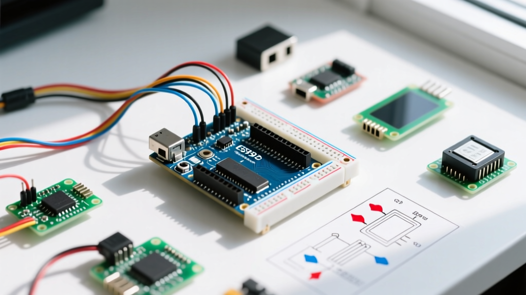
When makers and engineers search for an Arduino Nano pin diagram, they are usually trying to map physical hardware connections to software library requirements. However, as of 2026, the "Nano" form factor encompasses three distinctly different silicon architectures. The physical pinout remains largely identical across the boards to maintain shield and breadboard compatibility, but the underlying microcontroller units (MCUs) dictate how community libraries interpret those pins.
Understanding the delta between the physical pin diagram and the software Board Support Package (BSP) is the single most common point of failure in community-driven projects. Below is a breakdown of the current Nano ecosystem and how their pin mappings affect library support.
| Board Variant | MCU & Architecture | 2026 Avg. Price | Library Compatibility Index | Core BSP Requirement |
|---|---|---|---|---|
| Nano (Classic/Clones) | ATmega328P (8-bit AVR) | $4.50 (Clone) / $22 (Official) | 99% (Legacy Standard) | Arduino AVR Boards |
| Nano Every | ATmega4809 (8-bit megaAVR) | $11.50 | 85% (Requires API compliance) | Arduino megaAVR Boards |
| Nano 33 IoT | SAMD21 + NINA-W102 (32-bit ARM) | $18.00 | 75% (3.3V logic limits) | Arduino SAMD Boards |
Decoding the Arduino Nano Pin Diagram for Software Mapping
A physical pin diagram shows you that A4 is SDA and A5 is SCL for I2C communication. But when you install a community library like Adafruit's SSD1306 OLED driver, the library does not look at the silk-screen on your board. It queries the pins_arduino.h file within your installed BSP. If your code and BSP are mismatched, the library will attempt to bit-bang or initialize hardware registers that do not exist on your specific Nano variant.
The A6 and A7 Analog-Only Trap
The most notorious edge case in the Arduino Nano pin diagram involves pins A6 and A7. On the classic ATmega328P Nano, these two pins are strictly analog inputs. They lack a digital data direction register (DDR) and cannot be used with digitalWrite() or digitalRead().
The Community Library Failure Mode: Many generic sensor libraries written by the community include auto-scanning routines that iterate through pins 0 to 19 (where A0-A7 are mapped to D14-D21). When the library attempts to set A6 (D20) as a digital output to test for a pull-up resistor, the ATmega328P silently ignores the command. The library then times out, throwing a generic "Sensor Not Found" error.
Expert Fix: If you are porting legacy code to a Nano Every, note that the ATmega4809 does support digital I/O on A6 and A7. Libraries that hardcode an exclusion for these pins will artificially limit your Nano Every's capabilities. Always check the library's GitHub issues for "megaAVR A6 A7" patches.
External Interrupt Mapping (INT0 vs. Pin Change)
Looking at the classic Nano pin diagram, you will see that pins D2 and D3 are marked with an asterisk or tilde, denoting hardware external interrupts (INT0 and INT1). Community libraries for rotary encoders (like the popular Encoder.h) historically hardcoded the ATmega328P's EICRA and EIMSK registers to achieve low-latency readings.
If you upload this legacy library to a Nano 33 IoT (SAMD21), the compilation will instantly fail because the ARM Cortex-M0+ uses the NVIC (Nested Vectored Interrupt Controller) instead of AVR registers. Modern, well-supported community libraries now rely on the abstracted attachInterrupt(digitalPinToInterrupt(pin), ISR, mode) API. Always verify that a library uses this API rather than direct register manipulation before committing to a pinout design.
Board Support Packages (BSPs) and Community Libraries
The bridge between the physical Arduino Nano pin diagram and third-party software is the BSP. In the Arduino IDE 2.x ecosystem, managing these cores is critical for library support.
- Arduino AVR Boards: The gold standard for the classic Nano. Almost every library on the Arduino Library Manager is tested against this core first.
- Arduino megaAVR Boards: Required for the Nano Every. Libraries that use direct PORT manipulation (like older versions of FastLED or Adafruit NeoPixel) will fail here because the 4809 uses
VPORT(Virtual Ports) mapped to memory, rather than the legacyPORTB/PORTCregisters. - Arduino SAMD Boards: Required for the Nano 33 IoT. The biggest hurdle here is logic voltage. The pin diagram shows 5V tolerance on some clone boards, but the official Nano 33 IoT is strictly 3.3V. Feeding 5V I2C signals into A4/A5 will destroy the SAMD21's GPIO matrix.
Engineer's Note on FastLED: If your Nano Every project uses addressable LEDs, you must use FastLED version 3.6.0 or newer. Earlier versions lack the
VPORTdefinitions required to map the Nano Every's pin diagram to the correct memory addresses, resulting in flickering or completely dead LED strips on pins D5-D10.
Real-World Troubleshooting: I2C and SPI Routing
When wiring up SPI peripherals (like SD card modules or TFT displays), the Arduino Nano pin diagram dictates the following hardware SPI pins:
- MOSI: D11
- MISO: D12
- SCK: D13
- SS (CS): D10 (User definable, but D10 must be set as OUTPUT for hardware SPI to function as a master on classic AVRs).
The Edge Case: On the classic Nano, if you forget to set pinMode(10, OUTPUT) in your setup(), the hardware SPI controller will default to Slave mode, and your SD card library will hang indefinitely during SD.begin(). The Nano Every and Nano 33 IoT do not have this specific hardware quirk, but community libraries often include the D10 workaround anyway.
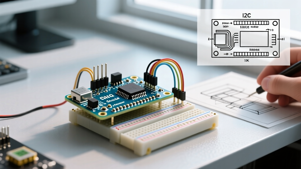
For I2C, the physical pins are A4 (SDA) and A5 (SCL). However, on the Nano 33 IoT, there is an internal I2C bus connecting the SAMD21 to the NINA-W102 Wi-Fi module. Community libraries that attempt to scan all I2C addresses using the Wire library will discover the Wi-Fi module at address 0x30. This is normal and should not be confused with an external sensor conflict.
Best Practices for Cross-Nano Code Portability
If you are developing a project that might be deployed on both classic Nanos (for cost-saving in bulk manufacturing using $4 clones) and Nano Everys (for production reliability), you must write your pin definitions conditionally. Relying purely on a static pin diagram will lead to fragmented codebases.
Use preprocessor directives to map your physical pin diagram to logical software names:
#if defined(__AVR_ATmega4809__)

  #define SENSOR_PIN A6 // Digital capable on Every

#else

  #define SENSOR_PIN A0 // Fallback for Classic Nano

#endif
By abstracting the physical pin diagram into logical macros, you ensure that community libraries receive the correct pin definitions regardless of the underlying silicon. For further reading on managing library dependencies across different architectures, refer to the Adafruit Guide to Arduino Libraries, which details how library managers resolve architecture-specific code.
Summary: Look Beyond the Silkscreen
The Arduino Nano pin diagram is merely a physical map; the true territory is defined by the microcontroller's datasheet and the community BSP. Whether you are dealing with the analog-only limitations of A6/A7 on the classic ATmega328P, the VPORT register shifts on the Nano Every, or the 3.3V logic constraints of the Nano 33 IoT, successful project execution requires aligning your physical wiring with the software's expectations. Always verify your library's architecture support matrix before finalizing your breadboard layout.
For official schematics and architecture-specific pin muxing tables, always consult the Arduino Nano Official Documentation and the Arduino megaAVR Core Repository on GitHub to ensure your 2026 projects are built on verified, up-to-date silicon data.