
The Evolution of the Nano: Why Pin Configuration Dictates Library Support
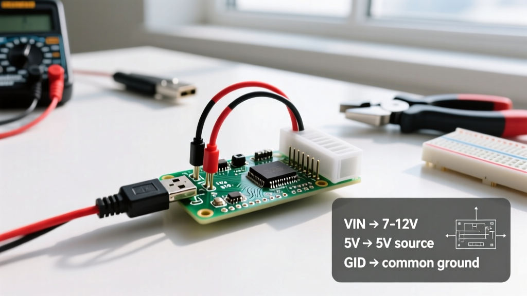
When the original Arduino Nano launched in 2008, its ATmega328P microcontroller and breadboard-friendly footprint established a standard that the maker community still relies on in 2026. However, understanding the pin configuration of Arduino Nano boards is no longer a simple matter of memorizing a single datasheet. Today, the 'Nano' form factor encompasses four distinct architectures: the Classic ATmega328P, the Nano Every (ATmega4809), the Nano 33 IoT (SAMD21), and the Nano RP2040 Connect.
While the physical headers remain identical, the internal silicon routing varies wildly. This divergence is the root cause of 90% of library compatibility issues discussed on community forums. Third-party libraries often rely on direct port manipulation or hardcoded timer registries that work flawlessly on the Classic Nano but fail silently or throw compilation errors on newer variants. In this guide, we dissect the pin configuration of Arduino Nano boards through the lens of community library support, providing actionable workarounds for the most common hardware-software conflicts.
The ATmega328P Baseline: Community Standards and Hardcoded Assumptions
The vast majority of Arduino libraries hosted on GitHub and the Library Manager were written with the Classic Nano's ATmega328P in mind. The community has built an ecosystem around its specific hardware limitations and features:
- Digital I/O: 22 pins (D0-D13, A0-A5).
- PWM Channels: 6 pins (D3, D5, D6, D9, D10, D11) driven by Timer0, Timer1, and Timer2.
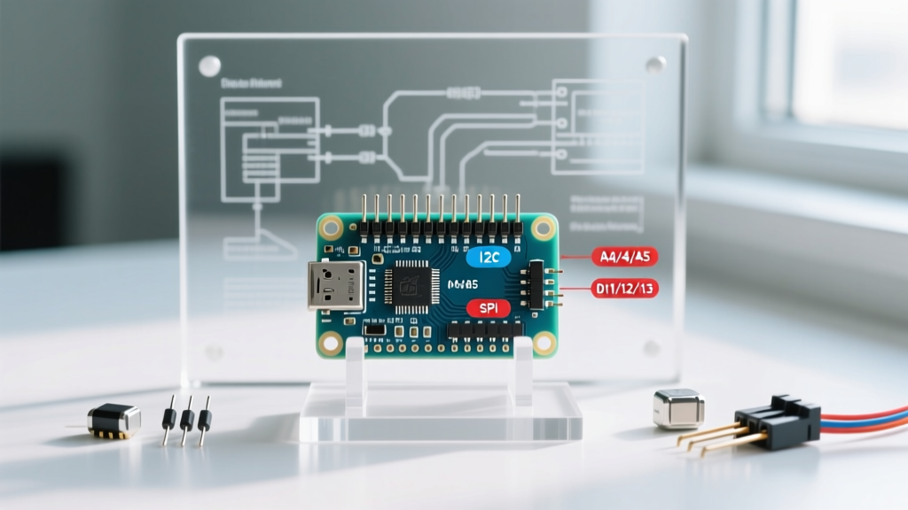
- Hardware SPI: Fixed to D11 (MOSI), D12 (MISO), and D13 (SCK).
- Hardware I2C: Fixed to A4 (SDA) and A5 (SCL).
Because the official Arduino Nano Documentation established these mappings early on, library developers frequently bypass the abstraction layer of digitalWrite() to achieve higher speeds. They write directly to the PORTB, PORTC, and PORTD registers. This optimization is a double-edged sword: it enables libraries like FastLED to push high-framerate data to LED strips, but it completely breaks when the underlying microcontroller changes.
Nano Variant Comparison Matrix (2026 Ecosystem)
Before importing a community library, you must identify your exact Nano variant. A library that requires hardware SPI will behave differently depending on the silicon. Below is a comparison of the current Nano lineup and how their pin configurations impact library support.
| Board Variant | MCU Core | Logic Level | I2C Pins (Default) | SPI Pins (Default) | PWM Pins | Avg. Price (2026) |
|---|---|---|---|---|---|---|
| Nano Classic ( & Clones) | ATmega328P | 5V | A4 (SDA), A5 (SCL) | D11, D12, D13 | 6 (D3,5,6,9,10,11) | $4.50 - $22.00 |
| Nano Every | ATmega4809 | 5V | A4 (SDA), A5 (SCL) | D11, D12, D13 | 5 (D3,5,6,9,10) | $11.00 - $14.00 |
| Nano 33 IoT | SAMD21G18 | 3.3V | A4 (SDA), A5 (SCL) | D11, D12, D13 | 11 (All D-pins except 0/1) | $18.00 - $21.00 |
| Nano RP2040 Connect | RP2040 | 3.3V | A4 (SDA), A5 (SCL) | D11, D12, D13 | All Digital Pins | $22.00 - $26.00 |
Resolving Community Library Conflicts by Pin Configuration
When a library fails to compile or behaves erratically, the issue usually traces back to a mismatch between the library's hardcoded pin assumptions and your Nano's actual silicon routing. Here is how the community addresses the most notorious conflicts.
1. The Direct Port Manipulation Trap (FastLED & Adafruit_NeoPixel)
Libraries designed for addressable LEDs require microsecond-precision timing. To achieve this, they use direct port manipulation. According to the FastLED Pin Notes Wiki, the ATmega328P uses specific memory addresses for its ports. If you upload a legacy NeoPixel library to a Nano Every (ATmega4809), the code will attempt to write to PORTD—a register that does not exist in the same memory space on the 4809. The result is a silent failure where the LED strip remains completely dark.
The Community Fix: Ensure you are using the latest versions of FastLED or Adafruit_NeoPixel. Modern versions use the Arduino core's digitalPinToPort() and portOutputRegister() macros, which abstract the hardware differences. If you are locked into an older library, you must use a Nano Classic or rewrite the library's timing loops to use hardware SPI (D11/D13) instead of bit-banging a random GPIO pin.
2. Timer1 Hijacking and the Servo Library
The standard Arduino Servo.h library relies on Timer1 to generate the 50Hz PWM signals required by hobby servos. On the Classic Nano, Timer1 is also responsible for hardware PWM on pins D9 and D10. When you attach a servo, the library disables analogWrite() functionality on D9 and D10. If your project uses a motor driver shield that expects PWM on D10, your motors will stutter or stop.
The Community Fix: Use the community-maintained ServoTimer2 library instead. This shifts the servo timing burden to Timer2, freeing up Timer1 and restoring full PWM functionality to D9 and D10. Note that doing this will disable PWM on D3 and D11, so plan your pin configuration accordingly.
3. Hardware I2C vs. Software Wire Mapping
On the Classic Nano, the I2C bus is physically hardwired to A4 (SDA) and A5 (SCL). However, on the Nano 33 IoT and RP2040 Connect, the native I2C buses are routed differently on the silicon, but the Arduino core uses a software multiplexer or pin-remapping to ensure A4 and A5 still function as I2C for backward compatibility. While this works for standard sensors, high-speed I2C devices (like certain LiDAR modules or OLEDs running at 1MHz) may experience clock-stretching failures due to the remapping overhead.
The Community Fix: For high-speed I2C on modern 3.3V Nanos, consult the variant-specific pinout diagrams to find the native, un-remapped SDA/SCL pins (often exposed on the underside pads or shared with specific digital pins) and initialize the Wire1 object instead of the default Wire object.
The A6 and A7 Edge Case: A Rite of Passage
Expert Warning: Pins A6 and A7 on the ATmega328P Nano are strictly analog inputs. They are physically connected only to the ADC (Analog-to-Digital Converter) multiplexer. They have no digital output drivers and no PWM capability.
Every year, thousands of makers fall into the A6/A7 trap. A common community library pattern for reading multiple sensors or driving multiple indicators involves a loop: for(int i=0; i<8; i++) { pinMode(A0+i, OUTPUT); }. On the Nano Classic, this will compile perfectly, but A6 and A7 will simply do nothing. Worse, if a library attempts to use analogWrite(A6, 128) expecting a PWM signal, it will fail silently. Always verify if your chosen library attempts to use A6/A7 as digital I/O, and if so, manually remap those functions to unused digital pins (D2, D4, D7, D8) in your initialization code.
Clone Boards, Bootloaders, and Community Support
In 2026, the market is flooded with $4.50 Nano clones utilizing the CH340G USB-to-Serial chip instead of the legacy FT232RL or official ATmega16U2. While the CH340G does not alter the GPIO pin configuration, it drastically affects how the community supports serial communication issues. Furthermore, many older clones ship with the 'Old Bootloader' (ATmegaBOOT) rather than the modern Optiboot.
If a community library relies on precise serial timing or utilizes the watchdog timer to reset the board, the Old Bootloader can cause the Nano to enter an infinite reset loop. When seeking help on forums like the Arduino subreddit or StackExchange, always specify your exact board variant, USB-Serial chip, and bootloader version. This information is just as critical to your pin configuration as the physical headers themselves.
Best Practices for Bulletproof Library Integration
To ensure your project survives the transition from prototype to production, follow these community-vetted rules when configuring your Nano's pins:
- Avoid Hardcoding in Sketches: Never write
pinMode(13, OUTPUT). Instead, use#define LED_PIN 13orconst int LED_PIN = 13;at the top of your sketch. This makes adapting to different Nano variants trivial. - Check Voltage Logic: If you are using a Nano 33 IoT or RP2040 Connect, remember that the pin configuration operates at 3.3V logic. Feeding 5V signals from a standard sensor into D2-D13 will fry the SAMD21 or RP2040 silicon. Use a bidirectional logic level converter (like the BSS138 MOSFET circuit) for any 5V I2C or SPI peripherals.
- Read the Library's
variantFolder: If a library is failing on a Nano Every, dive into the library's source code and look for#if defined(__AVR_ATmega328P__). If the developer hasn't included the__AVR_ATmega4809__macro, you will need to fork the library and update the port registers, or submit an issue to the maintainer.
By deeply understanding the pin configuration of Arduino Nano hardware and how community libraries interact with those specific silicon pathways, you can bypass the most frustrating roadblocks in embedded development. Whether you are driving APA102 LEDs via hardware SPI or multiplexing I2C sensors, respecting the underlying architecture is the key to stable, professional-grade DIY electronics.