
The Anatomy of Arduino Nano Interrupt Pins
When designing time-critical embedded systems—such as high-resolution rotary encoders, ultrasonic flow meters, or IR signal decoders—polling loops simply cannot keep up. Hardware interrupts allow the microcontroller to immediately pause its main routine, execute an Interrupt Service Routine (ISR), and return, ensuring zero missed pulses. However, not all Nano boards handle interrupts equally.
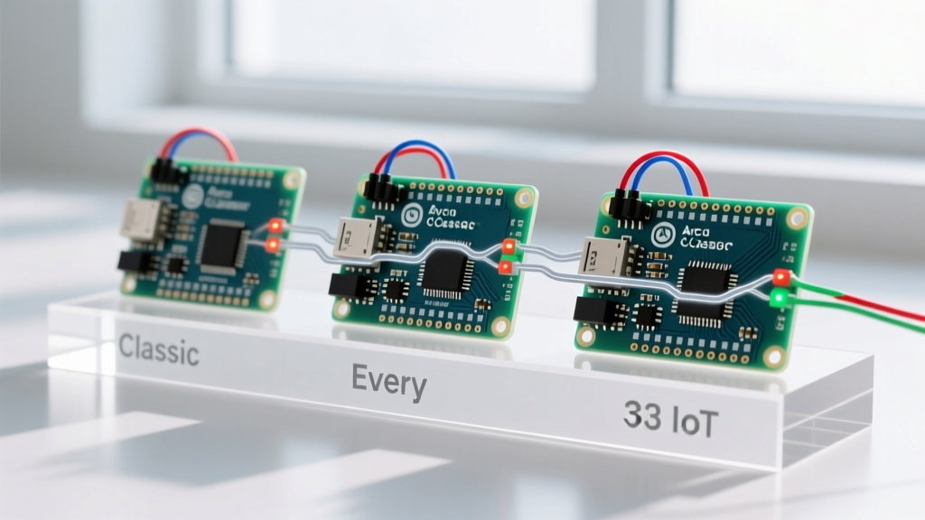
As of 2026, the Arduino Nano ecosystem has fractured into three distinct architectural silos: the legacy Classic Nano (ATmega328P), the modernized Nano Every (ATmega4809), and the ARM-based Nano 33 IoT (SAMD21). Understanding the specific interrupt pin mappings, hardware limitations, and register-level behaviors of each board is critical for preventing missed counts and system deadlocks.
Classic Arduino Nano (ATmega328P): The Legacy Limitation
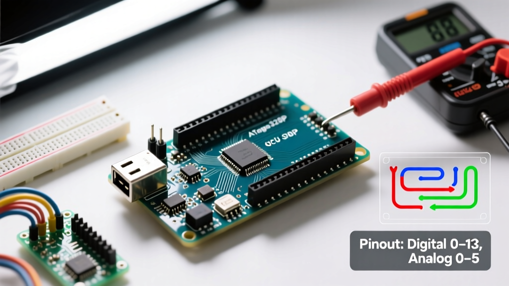
The original Arduino Nano relies on the Microchip ATmega328P microcontroller running at 16 MHz. This yields an instruction cycle of 62.5 nanoseconds. However, its external interrupt architecture is notoriously rigid.
Hardware External Interrupts (INT0 & INT1)
The Classic Nano only supports native hardware external interrupts on two pins:
- D2 (INT0)
- D3 (INT1)
These pins can be configured to trigger on LOW, CHANGE, RISING, or FALLING edges using the standard attachInterrupt(digitalPinToInterrupt(pin), ISR, mode) function. According to the official Arduino interrupt documentation, these are the only pins that map directly to the dedicated INT0 and INT1 vectors in the AVR interrupt vector table.
Pin Change Interrupts (PCINT): The Workaround
If your project requires more than two interrupt-driven inputs (e.g., a robot with four wheel encoders), you must use Pin Change Interrupts (PCINT). The ATmega328P groups its I/O pins into three ports, each sharing a single interrupt vector:
| Port | PCINT Range | Arduino Nano Pins | Control Register |
|---|---|---|---|
| PORTB | PCINT0-7 | D8 - D13 | PCMSK0 |
| PORTC | PCINT8-14 | A0 - A5 | PCMSK1 |
| PORTD | PCINT16-23 | D0 - D7 | PCMSK2 |
The Edge Case: PCINTs only trigger on any logic change. They do not natively support RISING or FALLING edge detection in hardware. You must read the pin state inside the ISR and compare it to a cached state variable to determine the direction of the edge. Furthermore, if any pin on PORTD changes state, the single PCINT2_vect fires, forcing your ISR to manually check which specific pin triggered the event. For complex projects, utilizing the Nick Gammon interrupt reference is highly recommended to manage bitwise register manipulation (PCICR and PCMSK) safely.
Arduino Nano Every (ATmega4809): The Architectural Leap
The Nano Every utilizes the ATmega4809, a completely different AVR architecture clocked at 20 MHz (50ns cycle). Microchip overhauled the GPIO and interrupt subsystem, effectively eliminating the Classic Nano's bottlenecks.
Every Pin is an Interrupt Pin
Unlike the 328P's shared PCINT groups, the ATmega4809 features configurable pin interrupts on every single GPIO pin. Each pin has its own dedicated PINnCTRL register where the ISC (Interrupt Sense Control) bits dictate the trigger condition (RISING, FALLING, BOTH, or LOW).
This means you can wire rotary encoders to D4, D5, D6, and D7, and assign distinct, isolated ISRs to each without writing a single line of bitwise port-masking code. The Arduino core abstracts this beautifully, allowing attachInterrupt() to work on any digital pin seamlessly.
Nano 33 IoT (SAMD21 Cortex-M0+): Asynchronous Mastery
For advanced users requiring extreme timing precision, the Nano 33 IoT uses the ARM Cortex-M0+ SAMD21G18A running at 48 MHz (20.8ns cycle). This board introduces the Nested Vectored Interrupt Controller (NVIC), a feature entirely absent in 8-bit AVR boards.
NVIC and Interrupt Priorities
On 8-bit AVR boards (Classic and Every), interrupts are strictly hierarchical based on their vector table position; an INT0 interrupt will always preempt a Timer1 interrupt. The SAMD21's NVIC allows you to assign software-defined priority levels (0 to 3). If you are reading a high-speed flow sensor while simultaneously maintaining a PID control loop via a hardware timer, you can configure the flow sensor's External Interrupt Controller (EIC) line to a higher priority than the timer, guaranteeing zero dropped pulses even under heavy CPU load.
Expert Note: The SAMD21 maps physical pins to 16 shared external interrupt lines (EXTINT[0] to EXTINT[15]). While you can attach an interrupt to almost any pin, you cannot use two pins that share the same EXTINT line simultaneously. Always consult the SAMD21 pin multiplexing datasheet before finalizing your PCB layout.
Board Comparison Matrix: Interrupt Capabilities
| Feature | Classic Nano (ATmega328P) | Nano Every (ATmega4809) | Nano 33 IoT (SAMD21) |
|---|---|---|---|
| Native External Int. Pins | 2 (D2, D3) | All GPIOs | Up to 16 (via EIC mapping) |
| Edge Detection Hardware | Yes (INT0/1), No (PCINT) | Yes (All GPIOs) | Yes (All EIC mapped) |
| Interrupt Prioritization | Fixed (Hardware Vector Table) | Fixed (Hardware Vector Table) | Programmable (NVIC 4-level) |
| ISR Context Switch Time | ~5.3 µs | ~4.8 µs | ~1.2 µs |
| Typical 2026 Market Price | $4 (Clone) / $24 (Official) | $12 (Official) | $20 (Official) |
Real-World Failure Modes & Troubleshooting
Working with Arduino Nano interrupt pins frequently exposes firmware engineers to severe edge cases. Below are the most common failure modes and their precise solutions.
1. The I2C Deadlock (Wire.h Conflict)
The Arduino Wire library relies on hardware interrupts to manage I2C bus states. If you attempt to read an I2C sensor (like an MPU6050) inside an ISR, and the I2C interrupt is masked by your active ISR, the microcontroller will permanently deadlock. Solution: Use the ISR solely to set a volatile boolean flag, and handle the I2C transaction in the main loop().
2. Serial Printing Inside ISRs
Calling Serial.println() inside an ISR on the Classic Nano will cause system lockups if the serial buffer fills up, as the serial transmission relies on the USART Data Register Empty (UDRE) interrupt, which is blocked while your ISR is executing. Solution: Never use blocking I/O functions inside an ISR. Keep ISR execution time under 5 microseconds.
3. Switch Bouncing on PCINTs
Mechanical switches and relays generate microsecond-level electrical noise when closing. On the Classic Nano's PCINT pins, this noise can trigger dozens of false interrupts per button press. Solution: Implement a hardware RC low-pass filter (e.g., 10kΩ resistor + 100nF capacitor) or enforce a software debounce timer using micros() to ignore subsequent triggers within a 5ms window.
Summary: Which Board Should You Choose?
If your project requires only one or two interrupt sources (like a single quadrature encoder or a tachometer), the Classic Nano remains a cost-effective, well-documented choice, especially if you are utilizing cheap third-party clones. However, if you are designing a multi-axis robotics platform or a complex MIDI controller requiring numerous asynchronous inputs, the Nano Every provides a vastly superior developer experience by turning every GPIO into a dedicated, edge-detecting interrupt pin without the headache of AVR bitmasking. For sub-microsecond timing requirements and DMA integration, the ARM-based Nano 33 IoT is the undisputed leader in the Nano footprint.