
Introduction to the Arduino Uno R3 Ecosystem
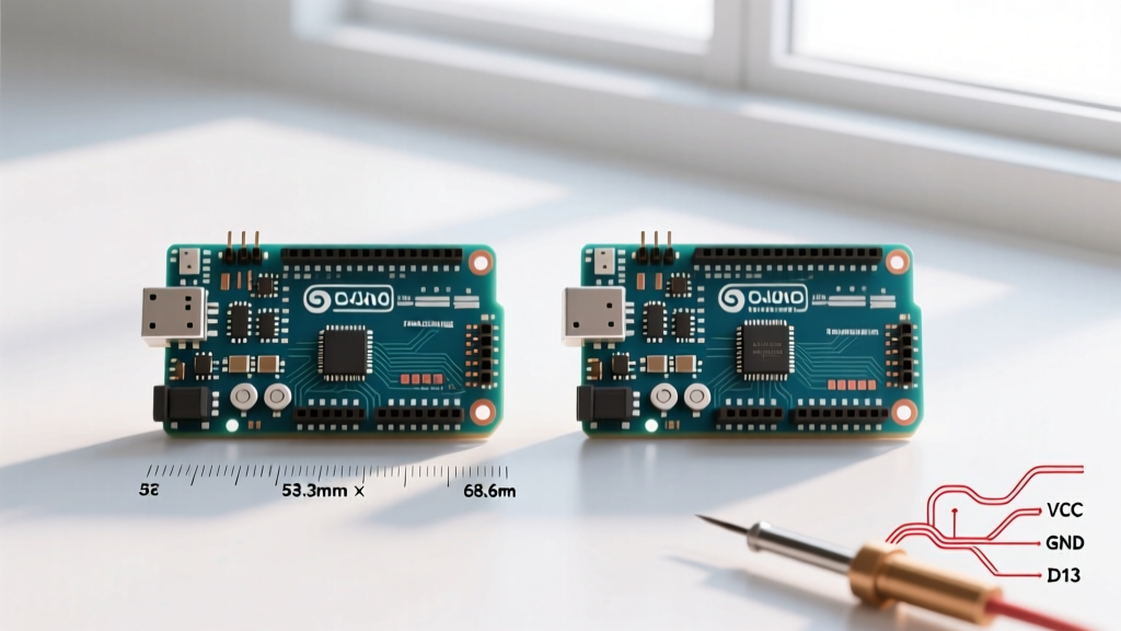
Learning to code Arduino Uno boards is the foundational rite of passage for every electronics hobbyist, student, and embedded systems engineer. At the heart of the classic Arduino Uno R3 is the Microchip ATmega328P-PU, an 8-bit AVR microcontroller running at 16 MHz. As of 2026, the genuine Arduino Uno R3 (model ABX00066) retails for approximately $27.60, while high-quality third-party clones like the Elegoo Uno R3 can be sourced for around $13.99. Regardless of which board you purchase, the process to code Arduino Uno hardware remains identical, relying on C++ compiled via the AVR-GCC toolchain and uploaded using the Avrdude utility.
This guide will walk you through the exact hardware prerequisites, software configuration, and coding paradigms required to successfully program your first sketch, while actively avoiding the common pitfalls that trap beginners.
Hardware Prerequisites: Genuine vs. Clone Boards
Before you write a single line of code, you must understand the physical hardware you are connecting to your computer. The most critical difference between a genuine Arduino and a clone lies in the USB-to-Serial converter chip.
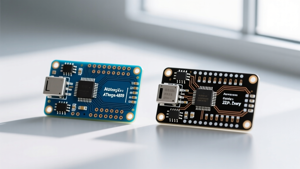
- Genuine Arduino Uno R3: Uses the ATmega16U2 chip for USB communication. This chip is natively recognized by Windows, macOS, and Linux without requiring third-party drivers.
- Clone Boards (e.g., Elegoo, HiLetgo): Typically use the CH340G or CH341A USB-to-Serial chip to reduce manufacturing costs. This requires a specific driver installation on Windows machines to be recognized by the IDE.
Note: Ensure you are using a data-capable USB cable. The genuine Uno requires a USB Type-A to Type-B cable (often called a printer cable). Many clones have shifted to USB Micro-B or Type-C. A common beginner failure mode is using a 'charge-only' cable, which lacks the internal D+ and D- data lines required for serial communication.
Step 1: Installing the IDE and Navigating the CH340 Driver Trap
To code Arduino Uno boards, you need an Integrated Development Environment (IDE). We recommend downloading the latest Arduino IDE 2.x from the official documentation portal. The 2.x branch introduces IntelliSense, real-time error checking, and a vastly improved serial monitor compared to the legacy 1.8.x versions.
The Windows 11 CH340 Driver Fix
If you purchased a clone board and your port selection is grayed out in the IDE, you have encountered the CH340 driver issue. Here is the exact fix for Windows 11:
- Download the official CH340 driver package from the chip manufacturer (WCH) or a trusted repository like SparkFun's Arduino installation guide.
- Plug your Uno clone into the PC via USB.
- Open Windows Device Manager and look under 'Other Devices' for an unknown USB-Serial device with a yellow warning triangle.
- Right-click the device, select Update driver, and point it to the downloaded CH340 folder.
- Once installed, the device will migrate to the 'Ports (COM & LPT)' section, typically assigning a COM port like COM3 or COM4.
Step 2: Anatomy of an Arduino Sketch
In the Arduino ecosystem, a program is called a 'sketch'. Every sketch requires two core functions to compile successfully. Understanding the execution flow of these functions is critical before you attempt to code Arduino Uno sensors or motors.
The Setup and Loop Paradigm
Unlike standard C++ desktop applications that start at main() and exit, an embedded microcontroller must run indefinitely. The Arduino core library abstracts the main() function, calling your two custom functions instead:
setup(): Executes exactly once when the board powers on or resets. This is where you configure pin modes, initialize serial communication, and set up I2C/SPI buses.loop(): Executes continuously, thousands of times per second, until power is removed. This handles state changes, sensor polling, and actuator control.
Step 3: Writing and Uploading Your First Blink Sketch
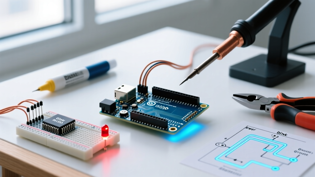
The 'Blink' sketch is the 'Hello World' of embedded systems. It verifies that your toolchain, compiler, and bootloader are communicating correctly. The Uno R3 features a surface-mount LED hardwired to digital pin 13 (mapped to LED_BUILTIN in the core library).
// Pin 13 has an LED connected on most Arduino boards.
int ledPin = LED_BUILTIN;

void setup() {
  // Initialize the digital pin as an output.
  pinMode(ledPin, OUTPUT);
}

void loop() {
  digitalWrite(ledPin, HIGH);  // Turn the LED on (5V)
  delay(1000);                 // Wait for 1000 milliseconds (1 second)
  digitalWrite(ledPin, LOW);   // Turn the LED off (0V)
  delay(1000);                 // Wait for a second
}
Upload Procedure:
- Click Tools > Board and select Arduino Uno.
- Click Tools > Port and select your active COM port (Windows) or
/dev/tty.usbmodem...(macOS). - Click the Upload button (right-pointing arrow). The TX/RX LEDs on the board will flicker rapidly as the compiled hex file is transferred via the Optiboot bootloader at 115200 baud.
Troubleshooting Common Upload Failures
When you code Arduino Uno projects, you will inevitably encounter Avrdude errors. Use this matrix to diagnose the failure mode:
| Error Message | Root Cause | Hardware/Software Solution |
|---|---|---|
avrdude: stk500_recv(): programmer is not responding |
The IDE cannot establish serial communication with the bootloader. | Verify the correct COM port. Press the physical RESET button on the Uno right as the IDE says 'Uploading'. Ensure no other software (like Cura 3D slicer) is hogging the serial port. |
Port grayed out in IDE menu |
OS does not recognize the USB-to-Serial chip. | Install CH340 drivers for clones. Swap the USB cable to rule out a charge-only wire. Try a different physical USB hub/port. |
Sketch too big; see https://www.arduino.cc/en/Guide/Troubleshooting |
Compiled binary exceeds the 32KB Flash memory limit. | Optimize code. Move large string literals into program memory using the F() macro or PROGMEM. |
avrdude: Expected signature for ATmega328P is 1E 95 0F |
Wrong board selected in IDE, or corrupted bootloader. | Ensure 'Arduino Uno' is selected, not 'Uno WiFi' or 'Nano'. If using an old clone, it might have an ATmega328 (without the 'P' for picoPower); select 'Uno' but use an older AVRDUDE config. |
Leveling Up: Moving Beyond the Delay Function
While the delay() function is fine for blinking an LED, it is a blocking function. When the ATmega328P executes delay(1000), it does literally nothing else for one second. It cannot read buttons, poll sensors, or update displays. To write professional-grade firmware, you must learn to code Arduino Uno sketches using non-blocking timing via the millis() function.
Expert Insight: Themillis()function returns the number of milliseconds since the board began running the current program. This value will overflow (reset to zero) after approximately 49.7 days. Always use subtraction (currentMillis - previousMillis >= interval) rather than addition to handle the rollover seamlessly.
unsigned long previousMillis = 0;
const long interval = 1000;
int ledState = LOW;

void setup() {
  pinMode(LED_BUILTIN, OUTPUT);
}

void loop() {
  unsigned long currentMillis = millis();

  if (currentMillis - previousMillis >= interval) {
    previousMillis = currentMillis;
    ledState = !ledState; // Toggle state
    digitalWrite(LED_BUILTIN, ledState);

    // You can now add sensor reading code here without waiting!
  }
}
Understanding ATmega328P Memory Constraints
When you code Arduino Uno boards, you are constrained by the physical silicon of the ATmega328P. According to the official Arduino hardware FAQ, the chip features three distinct memory pools:
- Flash Memory (32 KB): Where your compiled sketch (instructions and constant data) lives. 0.5 KB is reserved for the Optiboot bootloader, leaving 31.5 KB for your code.
- SRAM (2 KB): Volatile memory used for dynamic variables, the call stack, and the heap. Running out of SRAM causes unpredictable crashes and reboots. Avoid using the
Stringclass; prefer fixed-size character arrays (char[]) to prevent heap fragmentation. - EEPROM (1 KB): Non-volatile memory that retains data when power is lost. Use this to store calibration values, Wi-Fi credentials, or device states. It has a write endurance of roughly 100,000 cycles.
Next Steps for Your Coding Journey
Now that you know how to successfully configure the IDE, navigate driver installations, and structure non-blocking code, you are ready to interface with the physical world. Your next step should be exploring the Uno's 10-bit Analog-to-Digital Converter (ADC) by wiring up a TMP36 temperature sensor or a B10K potentiometer to the A0-A5 pins, utilizing the analogRead() function to map 0-5V signals into 0-1023 integer values.