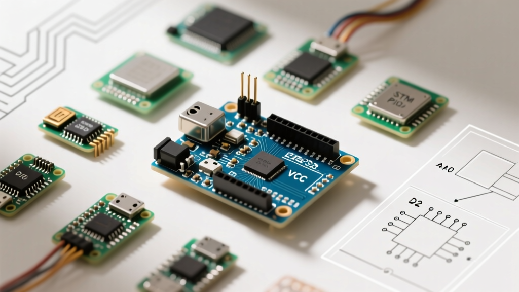

Beyond the Silkscreen: Why Pin Mapping Matters for Migration
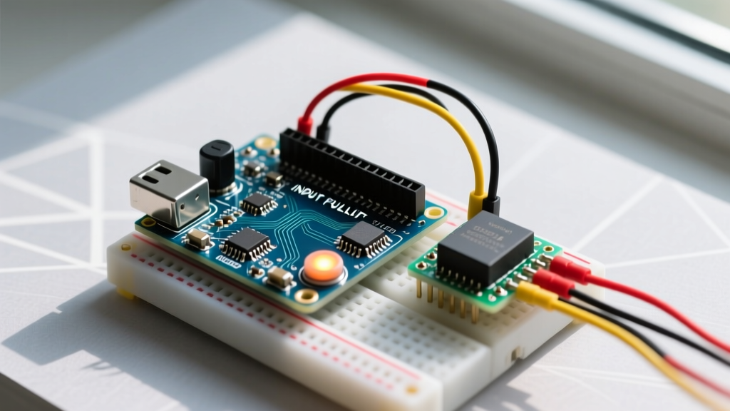
Memorizing the arduino uno pins description is a rite of passage for every electronics hobbyist. The ATmega328P-PU microcontroller at the heart of the Uno Rev3 offers a forgiving, 5V-tolerant, and rigidly mapped I/O layout that makes prototyping effortless. However, as projects evolve from blinking LEDs to IoT-connected sensor arrays, makers inevitably hit the Uno's hardware ceilings: limited RAM (2KB), lack of native wireless, and a modest 16MHz clock speed.
When you migrate to advanced platforms like the Espressif ESP32-S3, the Raspberry Pi Pico 2 (RP2350), or STM32 'Blue Pill' boards, the physical pinout changes drastically. More importantly, the underlying peripheral architectures shift. This guide uses the foundational Arduino Uno pins description as a baseline to map your existing knowledge to modern 3.3V microcontrollers, highlighting critical voltage traps, peripheral remapping, and logic-level translation strategies for 2026.
⚠️ The 5V to 3.3V Migration Trap: The Arduino Uno operates at 5V logic. Modern MCUs (ESP32, RP2040/RP2350, STM32) operate at 3.3V. Connecting a 5V Uno sensor output directly to an ESP32 GPIO will permanently destroy the ESP32's silicon. Always use logic level shifters when migrating legacy 5V peripherals.Digital I/O and Hardware Interrupt Mapping
The Uno features 14 digital I/O pins (D0-D13). On the ATmega328P, hardware interrupts are strictly limited to D2 (INT0) and D3 (INT1). If you are migrating a project that uses multiple rotary encoders, anemometers, or flow sensors, the Uno forces you to use pin-change interrupts (PCINT), which are complex to code and prone to jitter.
Migration Matrix: Digital I/O and Interrupts
| Feature | Arduino Uno (ATmega328P) | ESP32-S3 (DevKitC-1) | Raspberry Pi Pico 2 (RP2350) |
|---|---|---|---|
| Total Digital GPIOs | 14 (D0-D13) | 45 (usable) | 26 (GPIO0-GPIO25) |
| Hardware Interrupt Pins | 2 (D2, D3) | All GPIOs | All GPIOs |
| Logic Level | 5V (TTL) | 3.3V | 3.3V |
| Max GPIO Source Current | 20 mA (40mA absolute max) | 40 mA (varies by pin group) | 50 mA (total package limit applies) |
When migrating to the ESP32, you must also avoid 'strapping pins' (e.g., GPIO0, GPIO3, GPIO45, GPIO46) during boot, as these dictate the boot mode and can cause your project to hang if pulled high or low by external sensors. According to the official Espressif ESP32-S3 documentation, improper handling of strapping pins is the number one cause of boot failures in migrated projects.
PWM and Timer Conflicts: The Hidden Migration Hurdle
In the standard Arduino Uno pins description, PWM (Pulse Width Modulation) is available on pins 3, 5, 6, 9, 10, and 11 (denoted by the tilde ~ symbol). What the silkscreen doesn't tell you is that these pins are tied to specific hardware timers:
- Timer0 (Pins 5, 6): Controls the
millis()anddelay()functions. Altering the PWM frequency on these pins will break all time-dependent Arduino core functions. - Timer1 (Pins 9, 10): 16-bit timer, often used by the
Servolibrary. - Timer2 (Pins 3, 11): 8-bit timer, often used by tone generation libraries.
Migration Insight: When moving to the Raspberry Pi Pico, PWM is not tied to specific pins. The RP2350 features 8 PWM slices, each with two channels, allowing PWM output on almost any GPIO. On the ESP32, hardware timers are abstracted away by the LEDC (LED Control) peripheral, meaning you can assign PWM to any available GPIO without breaking core timing functions.
Analog Inputs and ADC Resolution Limits
The Uno provides 6 analog inputs (A0-A5) with a 10-bit resolution, yielding values from 0 to 1023. The reference voltage is strictly tied to the 5V rail (unless using the AREF pin). Furthermore, A4 (SDA) and A5 (SCL) are hardcoded to the I2C bus.
ADC Migration Realities
Modern MCUs boast higher ADC resolutions, but they come with distinct caveats that catch migrating developers off guard:
- ESP32 ADC Non-Linearity: The ESP32 features a 12-bit ADC (0-4095). However, the ADC is notoriously non-linear at the voltage extremes (below 0.15V and above 3.1V). If your Uno project relies on precise voltage divider readings near the 5V rail, migrating to an ESP32 will require software calibration curves or an external I2C ADC like the ADS1115.
- Pico ADC Channel Limits: While the Pico has a 12-bit ADC, it only exposes three usable ADC channels (GPIO26, GPIO27, GPIO28) plus one internal temperature sensor. If your Uno project uses A0 through A4, you will need to multiplex or add an external ADC when migrating to the Pico.
Power Pins: Current Budgeting Across Platforms
A critical, often overlooked aspect of the Arduino Uno pins description is the power rail limitations. The Uno's 3.3V pin is fed by an onboard linear regulator (typically an LP2985 or similar) that maxes out at 50mA.
Expert Tip: Many makers accidentally fry their Uno's 3.3V regulator by plugging in a 3.3V ESP8266 module or an nRF24L01 radio directly into the Uno's 3.3V pin. These modules draw 150mA-300mA during transmission, instantly overheating the Uno's LDO.
When migrating your project, the power architecture changes significantly:
- Raspberry Pi Pico (RP2040/RP2350): Uses an RT6154B buck-boost converter capable of supplying ~300mA on the 3.3V out pin, making it safe for most radios and sensors.
- ESP32 DevKit V1: Uses an AMS1117-3.3 LDO. While rated for 800mA, it lacks adequate heatsinking on cheap clones and will thermally throttle around 300mA. For high-current 3.3V needs, power the peripherals directly from a dedicated buck converter.
Communication Protocols: Remapping I2C, SPI, and UART
On the Uno, hardware communication buses are locked to specific pins. Migration requires rewriting pin definitions and understanding bus capacitance.
I2C Pull-Up Resistor Recalculation
The Uno operates I2C at 5V. Standard 4.7kΩ pull-up resistors work fine for 100kHz Standard Mode. When migrating to a 3.3V MCU (like the Pico or ESP32), the lower voltage means the I2C lines rise slower due to parasitic capacitance. To maintain a sharp signal edge at 400kHz Fast Mode on a 3.3V system, you must drop the pull-up resistors to 2.2kΩ or even 1kΩ depending on bus capacitance.
SPI Pin Mapping Matrix
| SPI Signal | Arduino Uno (Hardware SPI) | ESP32 (Default VSPI) | Raspberry Pi Pico (SPI0) |
|---|---|---|---|
| MOSI (COPI) | D11 | GPIO 23 | GPIO 19 |
| MISO (CIPO) | D12 | GPIO 19 | GPIO 16 |
| SCK | D13 | GPIO 18 | GPIO 18 |
| SS (CS) | D10 | GPIO 5 | GPIO 17 |
Logic Level Translation: Bridging the 5V/3.3V Divide
If you are migrating a project but keeping legacy 5V peripherals (like the HC-SR04 ultrasonic sensor, DS18B20 temperature sensors, or 5V WS2812B LED strips), you must translate the logic levels. As detailed in the Texas Instruments TXB0108 datasheet, auto-direction sensing transceivers are ideal for complex buses, but simpler MOSFET-based shifters work for basic GPIO.
Shifter Selection Guide for Migration
- BSS138 MOSFET Bidirectional Shifter (~$2.50 for 5-pack): Excellent for I2C and slow GPIO (<100kHz). Fails at high-speed SPI or driving WS2812B LEDs due to capacitance and slow rise times.
- TI TXB0108 Breakout (~$4.50 - $6.00): Features auto-direction sensing and high drive strength. Capable of handling SPI displays (like the ILI9341) at up to 20MHz. Essential for migrating 5V SPI TFT screens to the ESP32.
- 74LVC245 (~$1.50): Unidirectional, high-speed. Perfect for stepping down 5V sensor outputs to 3.3V MCU inputs.
Step-by-Step Platform Migration Checklist
Before you desolder your ATmega328P and wire up an ESP32 or Pico, run through this hardware validation checklist:
- Audit Voltage Tolerances: List every component. Identify any 5V-only sensors and procure TXB0108 or BSS138 level shifters.
- Remap Hardware Interrupts: Update your code. Remove
attachInterrupt(digitalPinToInterrupt(2), ...)and map to the new MCU's native GPIO interrupt API. - Recalculate ADC Math: Change your analog read scaling. A 10-bit Uno reads 1023 at 5V (4.88mV per step). A 12-bit Pico reads 4095 at 3.3V (0.8mV per step). Update all voltage-divider formulas.
- Verify I2C Pull-Ups: Remove 5V 4.7kΩ pull-ups and install 3.3V 2.2kΩ pull-ups on the SDA/SCL lines of the new board.
- Check Boot Strapping: Ensure no external sensors are pulling the ESP32's GPIO0 or GPIO12 low/high during power-on, which will force the chip into flash-download mode.
Frequently Asked Questions (FAQ)
Can I use the Arduino IDE to program the ESP32 and Pico using Uno pin numbers?
No. While the Arduino IDE supports both the ESP32 and Raspberry Pi Pico cores, the pin numbering maps directly to the silicon's GPIO numbers, not the Uno's D0-D13 silkscreen. You must rewrite your pin definitions to match the target board's physical GPIO layout.
Why does my migrated I2C OLED display work on the Uno but fail on the Pico?
The Uno's ATmega328P has internal pull-up resistors that are sometimes (incorrectly) relied upon by hobbyists who forget external I2C pull-ups. The Raspberry Pi Pico's RP2040/RP2350 I2C controllers strictly require external physical pull-up resistors (2.2kΩ to 3.3V) to function. As noted in the Arduino Uno Rev3 hardware documentation, relying on internal pull-ups for I2C is out of spec and will reliably fail on modern 3.3V architectures.
Is the 5V pin on the Uno an input or output?
It is both, but with caveats. If powering the Uno via USB or the barrel jack, the 5V pin is an output (limited to ~500mA via USB). If you are powering the Uno by feeding 5V directly into the 5V pin, you are bypassing the onboard regulator. This is common in custom PCBs but dangerous if you accidentally plug in the USB cable simultaneously, causing a 5V rail conflict that can destroy your PC's USB port.