
The Enduring Relevance of the ATmega2560 in High-I/O Systems
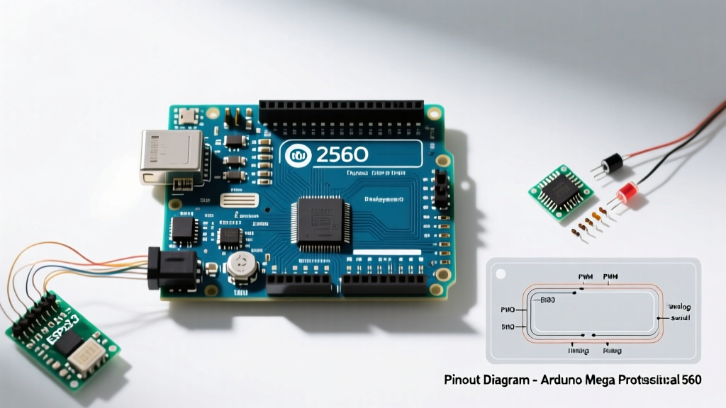
While modern microcontrollers like the ESP32-S3 and Raspberry Pi Pico dominate the IoT and high-speed processing spaces in 2026, the Arduino Mega 2560 remains the undisputed workhorse for projects requiring massive amounts of 5V-tolerant digital I/O. Driven by the Microchip ATmega2560 chip, this board offers 54 digital input/output pins and 16 analog inputs. However, simply having a high pin count does not guarantee project success. Understanding the specific Arduino Mega 2560 pinout—including hardware interrupt limitations, PWM distribution, and current sourcing capabilities—is critical for determining whether this board is actually suitable for your next robotics, CNC, or environmental monitoring build.
This project suitability analysis breaks down the physical and electrical realities of the Mega 2560, moving beyond basic tutorials to explore edge cases, failure modes, and optimal use-case matrices.
Decoding the Architecture: Beyond the Silkscreen
The Mega 2560 Rev3 layout is standardized, but its internal routing dictates how you must allocate resources. According to the official Arduino hardware documentation, the board features four hardware UARTs, a significant advantage over the Uno's single serial port.
Communication and Protocol Headers
- Hardware Serial: Pins 0/1 (Serial), 14/15 (Serial1), 16/17 (Serial2), and 18/19 (Serial3). This allows simultaneous communication with a PC, a GPS module, an RS485 transceiver, and a secondary microcontroller without relying on unstable software serial libraries.
- I2C Bus: Pins 20 (SDA) and 21 (SCL). Crucially, the Rev3 board also routes these to the dedicated 4-pin header near the USB port, ensuring compatibility with modern sensor shields.
- SPI Bus: Pins 50 (MISO), 51 (MOSI), 52 (SCK), and 53 (SS). Unlike the Uno, the SPI pins on the Mega are not routed to the ICSP header alone; they are broken out to the digital header, which frequently causes conflicts if users attempt to use pins 50-52 as standard digital I/O while an SPI shield is attached.
PWM and Interrupt Limitations
Despite having 54 digital pins, only 15 support hardware Pulse Width Modulation (PWM): pins 2 through 13, and 44 through 46. If your project requires driving 20 independent servos or dimmable LED channels via hardware PWM, the Mega 2560 will bottleneck, forcing you to implement software-based PWM or external PCA9685 I2C drivers.
Furthermore, external hardware interrupts are restricted to just six pins: 2, 3, 18, 19, 20, and 21. High-speed rotary encoders or multi-axis CNC limit switches must be carefully mapped to these specific pins to avoid polling latency.
Project Suitability Matrix
Not all high-pin-count projects are created equal. The following matrix evaluates the Mega 2560's suitability for common complex builds based on its specific pinout and electrical characteristics.
| Project Type | I/O Demand | Suitability Score | Primary Pinout Bottleneck |
|---|---|---|---|
| 3D Printer (RAMPS 1.4) | High (Digital + Analog) | 9.5/10 | ADC speed for high-res thermistors |
| 6-Axis CNC Router | Very High | 6/10 | Lack of 6 dedicated hardware interrupt pins for encoders |
| Smart Home Relay Hub | High (Digital) | 8/10 | Total VCC current limit when driving relay coils directly |
| Multi-Sensor Weather Station | Medium (Analog) | 7/10 | 10-bit ADC resolution limits precision barometric logging |
Deep Dive: High-Demand Project Scenarios
Scenario A: 3D Printing and the RAMPS 1.4 Shield
The most ubiquitous application for the Mega 2560 is driving 3D printers via the RAMPS 1.4 shield and Marlin firmware. The Marlin hardware documentation relies heavily on the Mega's specific analog and digital mapping. For instance, the X-axis stepper utilizes Pin 54 (A0) for steps, Pin 55 (A1) for direction, and Pin 38 for enable. Thermistors map to the analog pins (typically A13, A14, and A15 on the RAMPS board).
Expert Insight: When building a custom printer controller without a RAMPS shield, avoid using pins 16 and 17 for endstops. These are tied to Hardware Serial2. If you accidentally trigger a serial interrupt while homing, the printer can suffer a layer shift. Use pins 2 and 3 (Interrupts 0 and 1) for critical Z-axis endstops to ensure sub-millisecond response times.
Scenario B: Multi-Channel Environmental Data Logging
With 16 analog inputs (A0-A15), the Mega seems ideal for logging data from an array of soil moisture, light, and temperature sensors. However, the internal ADC (Analog-to-Digital Converter) is multiplexed and limited to 10-bit resolution (0-1023). When rapidly polling all 16 channels, ghosting and crosstalk can occur due to the internal sample-and-hold capacitor not fully discharging between reads.
Actionable Fix: If your project requires high precision across multiple analog channels, do not rely solely on the ATmega2560's internal ADC. Utilize the I2C pins (20/21) to connect an external 16-bit ADC like the Texas Instruments ADS1115, reserving the Mega's analog pins strictly for basic threshold triggers.
Hardware Edge Cases and Failure Modes
Understanding the electrical limits of the ATmega2560 microchip is just as important as memorizing the pinout. Ignoring these limits leads to catastrophic board failure.
The 5V vs. 3.3V Logic Level Trap
The Mega 2560 operates at 5V logic. In 2026, the vast majority of advanced sensors, wireless modules (like the ESP-01 or nRF24L01), and displays operate at 3.3V. Connecting a 3.3V module's TX pin directly to a Mega's 5V RX pin (e.g., Pin 14) will degrade the module over time or destroy it instantly. You must use a bidirectional logic level converter (such as a BSS138 MOSFET-based shifter) on all communication lines.
Current Sourcing and the Polyfuse
Each I/O pin can safely source or sink 20mA (absolute maximum 40mA). More importantly, the total current drawn from all VCC and GND pins combined must not exceed 200mA. A common failure mode occurs when users wire five standard 5V relays directly to the Mega's 5V rail. The combined coil draw exceeds the USB polyfuse limit (500mA) or the onboard 5V linear regulator's thermal shutdown threshold, causing the board to randomly reset during operation.
Rule of Thumb: Never drive inductive loads (relays, solenoids, motors) directly from the Mega 2560's digital pins. Always use logic-level MOSFETs (like the IRLZ44N) or optocouplers, and power the loads from an independent external power supply, sharing only the GND with the Mega.
When to Ditch the Mega: Modern Alternatives
Despite its massive I/O count, the Mega 2560's 16MHz clock speed and 8KB SRAM are severe limitations for modern audio processing, fast Fourier transforms (FFT), or high-speed camera interfacing. Consider these alternatives based on your pinout needs:
- Teensy 4.1 ($35 - $42): Features an ARM Cortex-M7 at 600MHz, 64 digital I/O pins, and native Ethernet. Ideal for high-speed DSP and complex robotics, but requires 3.3V logic level shifting.
- ESP32-S3-DevKitC ($8 - $12): Offers dual-core processing, Wi-Fi/Bluetooth, and roughly 45 usable GPIOs. Excellent for IoT hubs, but lacks the 5V tolerance and robust analog-to-digital stability of the Mega.
Expert Wiring Tips for Clean Mega 2560 Builds
To ensure long-term reliability in industrial or permanent installations, abandon the breadboard and Dupont wire approach.
- Use Screw Terminal Shields: Boards like the Cytron MakerDrive or generic Mega Screw Terminal shields allow you to terminate 22 AWG to 14 AWG wires securely, preventing vibration-induced disconnects in CNC environments.
- Custom PCB Prototyping: For production runs, design a custom PCB that accepts the Mega 2560 as a through-hole component (using 2x18 and 2x8 female headers). This reduces the overall footprint by 40% compared to stacking shields.
- Separate Power Domains: Use a buck converter (like the LM2596) to step down a 12V or 24V main supply to 5V for the Mega's VIN pin. Bypass the onboard linear regulator entirely to eliminate thermal throttling when powering the board in an enclosed chassis.
Final Verdict
The Arduino Mega 2560 pinout is a masterclass in legacy compatibility and raw I/O volume. For projects requiring extensive 5V digital routing, multiple hardware serial ports, and established shield ecosystems like RAMPS, it remains highly relevant. However, engineers must respect its 10-bit ADC limitations, strict 20mA per-pin current ceilings, and 5V logic requirements. By mapping your project's specific interrupt and PWM needs against the board's physical silkscreen, you can leverage the Mega 2560 to build robust, high-channel-count systems that stand the test of time.