
The Core Challenge: Pulse Generation on a 16MHz Microcontroller
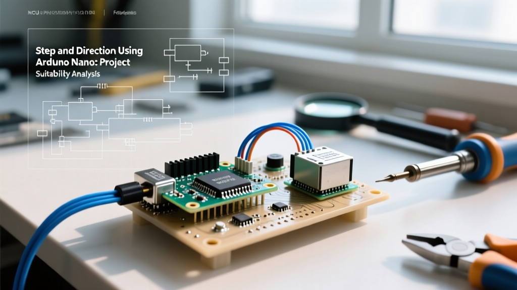
When designing custom motion control systems, generating precise step and direction signals is the foundational requirement. The step/dir interface remains the undisputed industry standard for driving external microstepping drivers like the TB6600, DRV8825, and TMC2209. But is the Arduino Nano the right brain for the job? Analyzing step and direction using Arduino Nano requires a deep dive into the ATmega328P's architectural limits, specifically its 16MHz clock speed, 2KB SRAM, and interrupt handling capabilities.
At 16MHz, a single clock cycle takes 62.5 nanoseconds. To generate a reliable step pulse, most industrial stepper drivers require a minimum pulse width of 2 to 5 microseconds. This means the microcontroller has roughly 32 to 80 clock cycles to set a pin HIGH, wait, and set it LOW. While this is trivial for a single motor, calculating trapezoidal acceleration profiles and generating synchronized pulse trains for 3 or 4 axes simultaneously pushes the ATmega328P to its absolute limits.
Hardware Constraints: Why the Nano's ATmega328P Matters
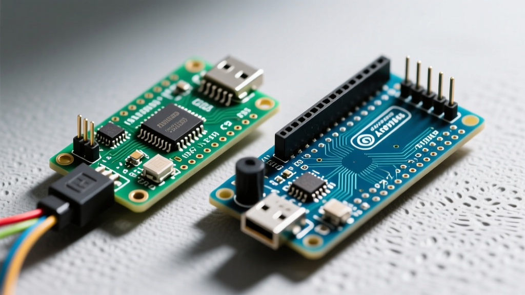
The Arduino Nano's suitability hinges entirely on its microcontroller and USB-to-serial architecture. As of 2026, genuine Nanos ship with the FT232RL USB chip, while the market is flooded with $4 to $6 clones utilizing the CH340G or CH340C chips. This distinction is critical for motion control.
Timer Interrupts vs. Delay Loops
Beginners often attempt to generate step pulses using delayMicroseconds(). This is a fatal flaw in motion control. Delay loops are blocking; while the Nano is delaying, it cannot read limit switches, parse incoming G-code, or update the serial buffer. Professional implementations rely on hardware timer interrupts (specifically Timer1 on the ATmega328P) to trigger step pulses in the background while the main loop handles kinematics and communication.
Expert Insight: The ATmega328P only has three hardware timers. Timer0 is reserved for Arduino's core
millis()anddelay()functions. Timer1 (16-bit) is typically hijacked by motion libraries for step generation, leaving only Timer2 (8-bit) for secondary tasks like spindle PWM control. If your project requires complex multi-axis coordination alongside high-frequency spindle control, you will quickly run out of hardware timers on the Nano.
Project Suitability Matrix: When to Choose the Nano
To determine if step and direction using Arduino Nano is appropriate for your specific build, compare your project requirements against the matrix below. Pricing reflects average 2026 market rates for hobbyist-grade components.
| Feature / Requirement | Arduino Nano (ATmega328P) | Arduino Mega 2560 | ESP32 Dev Board |
|---|---|---|---|
| Max Step Rate (Single Axis) | ~30 kHz | ~40 kHz | ~200 kHz+ |
| Simultaneous Axes | 3 (X, Y, Z) | 4 to 6 | 6+ |
| Logic Level Output | 5V (Native) | 5V (Native) | 3.3V (Requires translation for some drivers) |
| Standard Firmware | GRBL v1.1 | Marlin / Custom | FluidNC / GRBL_ESP32 |
| Approx. Board Cost | $5 (Clone) / $26 (Genuine) | $14 (Clone) / $45 (Genuine) | $6 - $9 |
| Best Use Case | Desktop CNCs, Laser Engravers, Camera Sliders | 3D Printers, Large Format CNCs | High-Speed Pick & Place, IoT-enabled CNCs |
Real-World Failure Modes and Edge Cases
Theoretical specs rarely survive contact with real-world electromechanical noise. When deploying step and direction using Arduino Nano, engineers frequently encounter the following failure modes:
- Optocoupler Bandwidth Degradation: Many high-power drivers like the TB6600 ($12-$15 per unit) use internal PC817 optocouplers for signal isolation. These optocouplers have a slow Current Transfer Ratio (CTR) and struggle to switch cleanly above 15-20 kHz. If you push the Nano to output 30 kHz step pulses, the optocoupler's rise and fall times will overlap, causing the driver to miss steps or stall entirely. Solution: Use direct-logic drivers like the DRV8825 or upgrade to drivers with high-speed 6N137 optocouplers.
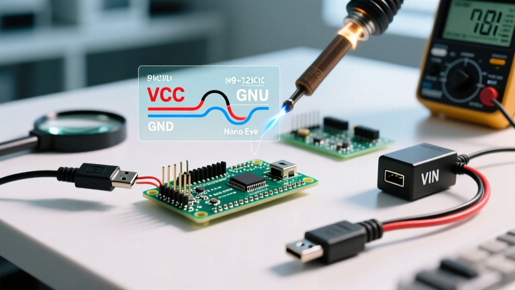
- USB Ground Loop Resets: Stepper motors generate massive back-EMF and ground noise. Because the Nano's USB port shares a common ground with its I/O pins, ground loops can induce voltage spikes on the USB data lines. This frequently causes the CH340G chip to lock up or the ATmega328P to brown-out and reset mid-job. Solution: Implement a star-ground topology, use galvanically isolated USB hubs, or power the Nano via the VIN pin (7-12V) while keeping the USB disconnected during operation.
- SRAM Buffer Overflows: The ATmega328P has only 2KB of SRAM. GRBL v1.1 uses roughly 1.2KB just for its internal planner and serial buffers. If you attempt to stream highly complex, micro-segmented G-code (such as 3D contouring from a CAM software) without proper flow control (like Grbl's realtime handshake), the Nano will drop characters, resulting in catastrophic toolpath deviations.
Wiring and Logic Level Translation: The 5V Advantage
One of the most compelling arguments for step and direction using Arduino Nano in 2026 is its native 5V logic. While the industry is shifting toward 3.3V microcontrollers (like the ESP32 and STM32), the vast majority of legacy and hobbyist stepper drivers (A4988, DRV8825, TB6560) are explicitly designed for 5V logic thresholds.
Connecting a 3.3V ESP32 directly to the STEP/DIR pins of an A4988 often results in unreliable triggering because the 3.3V HIGH signal falls dangerously close to the driver's 2.5V logic threshold, leaving zero noise margin. The Nano's 5V output provides a robust 2.5V noise margin, eliminating the need for bidirectional logic level shifters (like the BSS138 or 74AHCT125) and simplifying your custom PCB or breadboard layout.
Recommended Pin Mapping for GRBL
If you are flashing GRBL onto the Nano, adhere strictly to the hardware-mapped interrupt pins to ensure maximum pulse fidelity:
- X-Axis Step/Dir: Pins D2 / D5
- Y-Axis Step/Dir: Pins D3 / D6
- Z-Axis Step/Dir: Pins D4 / D7
- Limit Switches: Pins D9, D10, D11 (Must utilize internal pull-up resistors via GRBL config)
Software Ecosystem: GRBL vs. AccelStepper
Your choice of firmware or library will dictate the Nano's performance ceiling. According to the official GRBL repository, the v1.1 firmware is heavily optimized for the ATmega328P, utilizing assembly-level optimizations for the step interrupt service routine (ISR). This allows GRBL to achieve smooth 3-axis interpolation at step rates up to 30 kHz, which is more than sufficient for standard NEMA 23 motors on a 1/16 microstepping driver.
Conversely, if you are building a custom application (like an automated camera slider or a winding machine) and opt for the AccelStepper library, you must manage your expectations. As noted in the Arduino Nano hardware documentation, the standard polling method (stepper.run()) inside the main loop is highly inefficient. If you use AccelStepper without configuring hardware timer interrupts, the maximum reliable step rate drops to roughly 4,000 steps per second. For custom high-speed projects, you must implement a timer-based interrupt approach to call the step function independently of the main loop.
Final Verdict: Is the Nano Enough for Your Build?
Step and direction using Arduino Nano remains a highly viable, cost-effective solution for specific project profiles in 2026. It is the undisputed champion for 3-axis desktop CNC routers, CO2 laser engravers, and custom single-axis automation where native 5V logic and GRBL compatibility are paramount. The availability of cheap CH340 clones makes it an economical choice for embedded, drop-in control boards.
However, if your project demands 4+ axis synchronization, high-speed pick-and-place kinematics, or Wi-Fi/Bluetooth connectivity for wireless G-code streaming, the Nano's 16MHz clock and 2KB SRAM will become a severe bottleneck. In those scenarios, migrating to an ESP32 running FluidNC or a 32-bit SKR board running Marlin is the necessary engineering decision. Evaluate your axis count, required step frequency, and logic voltage requirements carefully before committing to the ATmega328P architecture.