
The Economics of the Arduino Nano 3 x Bundle
When transitioning from single-board prototypes to distributed systems, purchasing an Arduino Nano 3 x bundle (a 3-pack of Nano boards) is one of the most cost-effective entry points into multi-node networking. As of early 2026, a genuine Arduino Nano retails for roughly $24.50 per unit. Conversely, a 3-pack of high-quality third-party clones (such as those from Elegoo or Rexqualis) typically costs between $14.99 and $18.50. While genuine boards support the open-source hardware ecosystem, modern clone boards have closed the reliability gap significantly, making them ideal for permanent installations where risking a $25 board on a remote sensor node is hard to justify.
However, setting up three distinct microcontrollers introduces unique hardware and firmware challenges that single-board tutorials completely ignore. In this guide, we will bypass the standard 'blink' tutorial and immediately configure your 3-pack into a 3-Node UART Environmental Daisy-Chain, utilizing hardware serial communication and I2C sensor arrays.
Pre-Flight: CH340 Drivers and Bootloader Quirks
Before wiring a single sensor, you must address the USB-to-Serial bridge chip. Genuine Nanos use the FTDI FT232RL or the 16U2 chip. Almost all 3-pack bundles utilize the WCH CH340G or the newer crystal-less CH340C. While Windows 11 (24H2) and macOS Sequoia often include generic CH340 drivers natively, they frequently fail to assign the correct COM port or throw a 'serial port busy' error during compilation.
- Windows Users: Download the official signed driver directly from the WCH CH340 Official Datasheet & Drivers page. Do not rely on third-party driver aggregators.
- macOS Users: The CH340C chip is generally plug-and-play on Apple Silicon (M1/M2/M3) running macOS 14+. If you have an older Intel Mac, you may need to adjust kernel extension security settings in the Recovery menu.
The 'Old Bootloader' Trap
When you plug in your first Nano from the 3-pack and attempt to upload code, you will likely encounter the classic avrdude: stk500_recv(): programmer is not responding error. This is rarely a hardware defect. Most clone manufacturers flash the legacy 19200-baud bootloader instead of the modern Optiboot (115200-baud) to save flash space. In the Arduino IDE 2.3.x, navigate to Tools > Processor and explicitly select ATmega328P (Old Bootloader). For a deeper dive into the hardware architecture, refer to the Arduino Nano Official Documentation.
Project: 3-Node UART Environmental Daisy-Chain
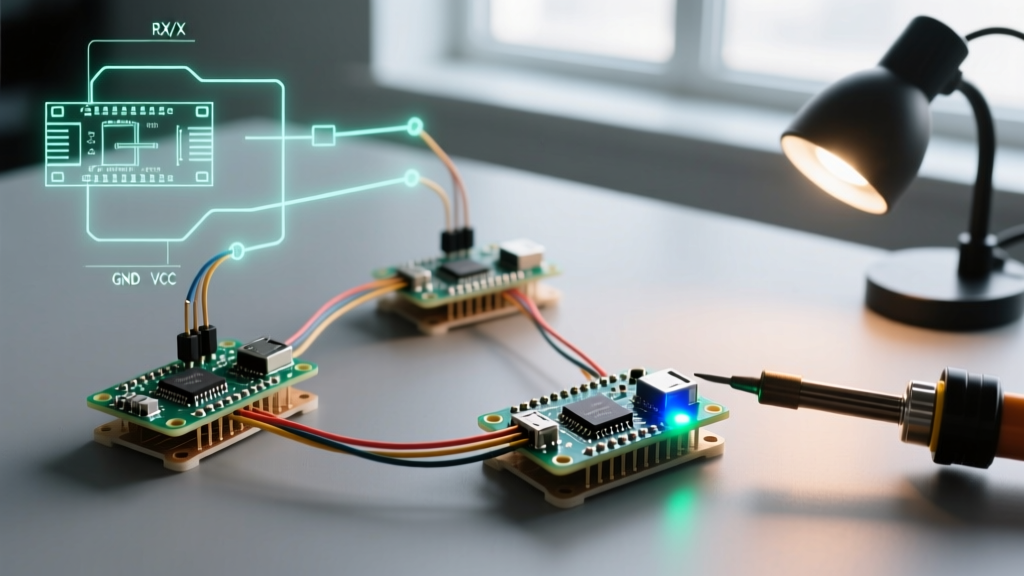
For our first project, we will build a distributed sensor network. Instead of using an I2C multiplexer (which adds hardware complexity and points of failure), we will use the Nano's hardware UART (Pins 0 and 1) to daisy-chain data. Node 1 reads its sensor and passes the data to Node 2. Node 2 appends its sensor data and passes it to Node 3. Node 3 acts as the Master, compiling the payload and pushing it to your PC via USB.
Required Bill of Materials (BOM)
- 3x Arduino Nano (ATmega328P-AU)
- 3x BME280 Breakout Boards (I2C compatible, 3.3V logic)
- 1x Breadboard and jumper wires
- 1x Micro-USB data cable (Strictly data-capable, not charge-only)
Wiring Matrix
The BME280 sensors communicate via I2C, while the nodes communicate via Hardware Serial. Because the Nano only has one hardware serial port, we dedicate it entirely to inter-node communication, avoiding the timing jitter of SoftwareSerial.
| Node Role | I2C Sensor (BME280) | UART TX (Pin 1) | UART RX (Pin 0) |
|---|---|---|---|
| Node 1 (Leaf) | SDA to A4, SCL to A5 | Connects to Node 2 RX | N/A (Leave floating) |
| Node 2 (Relay) | SDA to A4, SCL to A5 | Connects to Node 3 RX | Connects to Node 1 TX |
| Node 3 (Master) | SDA to A4, SCL to A5 | Connected to PC via USB | Connects to Node 2 TX |
Note: Ensure all three Nanos share a common Ground (GND) connection. Without a common ground reference, the UART serial lines will experience massive packet loss and framing errors.
Firmware Implementation: The UART Chain
To make this network robust, we use a structured payload format. Each node will output a comma-separated string terminated by a newline character (\n). We will utilize the SparkFun BME280 Hookup Guide library for sensor polling.
Node 1 & Node 2: Transmitter Logic
Nodes 1 and 2 listen for incoming serial data from the previous node, append their own BME280 temperature reading, and forward the combined string. Here is the core logic for the relay nodes:
#include <Wire.h>
#include <SparkFunBME280.h>

BME280 mySensor;
String incomingPayload = "";

void setup() {
  Serial.begin(9600); // Hardware UART for daisy-chain
  Wire.begin();
  mySensor.setI2CAddress(0x76); // Change to 0x77 if needed via solder jumper
  mySensor.beginI2C();
}

void loop() {
  if (Serial.available()) {
    char c = Serial.read();
    if (c == '\n') {
      // Append local sensor data and forward
      float tempC = mySensor.readTempC();
      Serial.print(incomingPayload + ",Node:" + String(tempC) + "\n");
      incomingPayload = ""; // Reset buffer
    } else {
      incomingPayload += c;
    }
  }
  delay(50); // Prevent watchdog resets on tight loops
}
Node 3: The Master Aggregator
Node 3 initiates the polling cycle. Every 5 seconds, it sends a 'ping' to Node 1, reads the final aggregated string, parses it, and prints it to the Arduino IDE Serial Monitor via the USB virtual COM port.
Expert Insight: Because Node 3 uses the USB port to talk to the PC, its hardware TX/RX pins are simultaneously tied to the USB bridge and Node 2. This works perfectly for half-duplex polling, but ensure you do not open the Serial Monitor while Node 3 is actively receiving a multi-byte string from Node 2, as the CH340 chip may inject a brief reset pulse on the DTR line, corrupting the incoming UART buffer.
Edge Cases: Why Your 3-Node Network Might Fail
Multi-node setups expose hardware flaws that single-board testing hides. If your network drops packets or resets randomly, investigate these three specific failure modes:
1. The 'Charge-Only' Cable Catastrophe
Over 60% of beginner UART failures stem from using a micro-USB cable lacking internal data lines (D+ and D-). If Node 3 fails to show up in the IDE port menu, or if the TX LED flashes but the Serial Monitor remains blank, swap the cable. A true data cable will have four internal wires; charge-only cables only have two.
2. I2C Address Collisions
Most cheap BME280 breakout boards default to the I2C address 0x76. Because each Nano has its own independent I2C bus, you can use the same address on all three boards without a collision. However, if you accidentally wire multiple sensors to a single Nano, the bus will lock up. Always verify the pull-up resistors on the SDA/SCL lines; many clone sensor boards include 4.7k pull-ups, and paralleling them across a shared bus drops the resistance too low for the ATmega328P's I2C drivers to pull high.
3. Voltage Regulator Brownouts
The Nano's onboard AMS1117-5.0 voltage regulator is rated for roughly 800mA, but it lacks adequate heatsinking. If you are powering all three Nanos from a single 9V wall adapter daisy-chained through the Vin pins, the middle board's regulator will overheat and trigger thermal shutdown within 4 minutes.
The 2026 Best Practice: Power distributed Nano networks by injecting regulated 5V directly into the 5V pin, completely bypassing the onboard linear regulators. This eliminates thermal throttling and reduces power waste by up to 40%.