
Understanding the ATmega2560 Interrupt Architecture
When building complex embedded systems, relying on digitalRead() polling loops is a recipe for missed signals and sluggish performance. This is where Arduino Mega interrupt pins become critical. By leveraging the underlying ATmega2560 microcontroller's interrupt architecture, your code can instantly pause its main routine to handle time-sensitive events—like a rotary encoder tick, a limit switch trigger, or a high-speed flow sensor pulse.
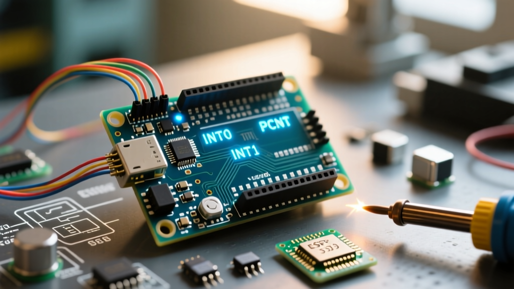
As of 2026, a genuine Arduino Mega 2560 Rev3 retails for roughly $48, while high-quality third-party clones (featuring the CH340 USB-to-serial chip) hover around $14 to $18. Regardless of the board variant, the silicon remains the same: the ATmega2560. This chip offers two distinct types of interrupts: dedicated External Hardware Interrupts (INT0-INT5) and Pin Change Interrupts (PCINT). Understanding the strict hardware mapping and edge cases of these pins is the difference between a robust industrial controller and a buggy prototype.
Hardware External Interrupts (INT0-INT5) Mapping
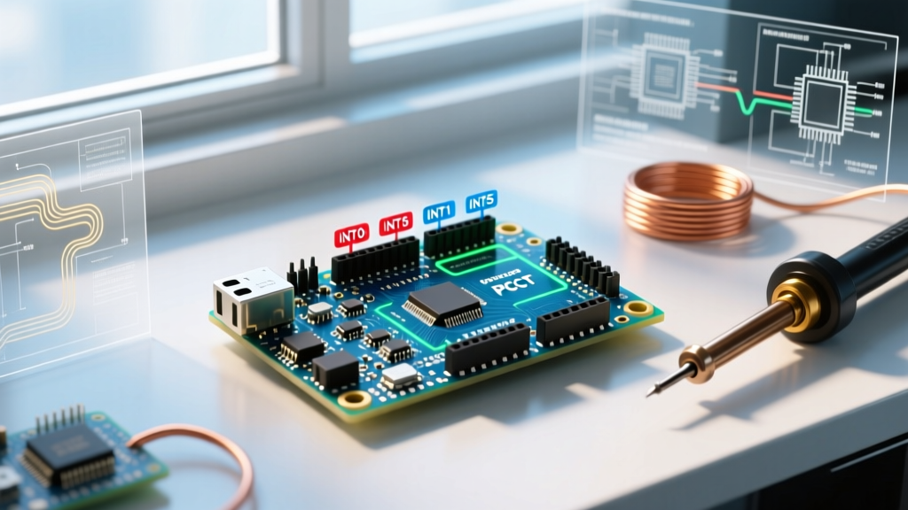
The ATmega2560 features six dedicated external interrupt pins. These are the most reliable and lowest-latency interrupt sources available on the board. They support specific trigger modes: LOW, CHANGE, RISING, and FALLING.
| Interrupt Vector | Arduino Digital Pin | Trigger Modes Supported | Common Use Case |
|---|---|---|---|
| INT0 | Pin 2 | LOW, CHANGE, RISING, FALLING | Rotary Encoders, Flow Sensors |
| INT1 | Pin 3 | LOW, CHANGE, RISING, FALLING | Limit Switches, Anemometers |
| INT2 | Pin 21 | LOW, CHANGE, RISING, FALLING | GPS PPS Signals |
| INT3 | Pin 20 | LOW, CHANGE, RISING, FALLING | External Fault Triggers |
| INT4 | Pin 19 | LOW, CHANGE, RISING, FALLING | Zero-Cross Detection |
| INT5 | Pin 18 | LOW, CHANGE, RISING, FALLING | High-Speed Counters |
To use these, you must map the physical pin to the interrupt vector using the digitalPinToInterrupt() macro. According to the official Arduino attachInterrupt documentation, the syntax is strictly: attachInterrupt(digitalPinToInterrupt(pin), ISR, mode);. Never pass the raw pin number directly into the first argument, as this will result in silent failures on the Mega.
The I2C Pin Conflict Edge Case (Pins 20 & 21)
A notorious trap for intermediate developers involves Arduino Mega interrupt pins 20 and 21. On the Mega 2560, these pins double as the primary I2C bus lines (SDA and SCL, respectively). They also map to INT3 and INT2.
If you are communicating with an I2C sensor (like a BME280 or MPU6050) and attempt to use pins 20 or 21 for hardware interrupts, you will introduce severe bus capacitance and logic conflicts, often crashing the I2C bus entirely. Actionable Advice: If your sensor has an INT/DRDY (Data Ready) pin, route it to Pin 2 or Pin 3. Reserve pins 20 and 21 exclusively for I2C communication, or use them as standard GPIO only if the I2C bus is completely disabled in your project.
Pin Change Interrupts (PCINT): Expanding Your Reach
What if your project requires monitoring 15 different limit switches, but you only have six hardware interrupt pins? The ATmega2560 solves this with Pin Change Interrupts (PCINT). Almost every digital and analog pin on the Mega supports PCINT, bringing the total number of interrupt-capable pins to over 80.
However, PCINTs come with architectural limitations that you must understand:
- Bank Triggering: PCINTs are grouped into banks (e.g., PCINT0-7, PCINT8-15). When any pin in a bank changes state, the single shared Interrupt Service Routine (ISR) for that entire bank fires.
- Trigger Mode: PCINTs only support the
CHANGEmode. They cannot natively trigger exclusively onRISINGorFALLINGedges at the hardware level. - Software Overhead: Because the ISR fires for the whole bank, your code must manually read the PIN register to determine exactly which pin caused the interrupt.
Writing raw PCINT register code (manipulating PCICR and PCMSK) is tedious and error-prone. For modern 2026 development, it is highly recommended to use optimized libraries like PinChangeInterrupt by NicoHood, which abstracts the register math while maintaining minimal overhead. You can review the underlying silicon capabilities in the Microchip ATmega2560 product datasheet.
Comparison Matrix: Hardware INT vs. PCINT
| Feature | Hardware Interrupts (INT0-INT5) | Pin Change Interrupts (PCINT) |
|---|---|---|
| Available Pins | 6 (Pins 2, 3, 18, 19, 20, 21) | 80+ (Almost all GPIO) |
| Trigger Modes | LOW, CHANGE, RISING, FALLING | CHANGE only |
| Latency | Lowest (Direct vector routing) | Slightly higher (Requires bank polling) |
| ISR Mapping | 1:1 (One pin, one ISR) | Many:1 (Entire bank shares one ISR) |
| Best For | High-speed encoders, precise timing | Button matrices, slow state changes |
Writing Bulletproof Interrupt Service Routines (ISRs)
The most common point of failure when utilizing Arduino Mega interrupt pins is poorly written ISR logic. An ISR is a hardware-level detour; while it executes, the main program is frozen, and other interrupts of lower priority are blocked.
The Golden Rule of ISRs: Get in, update a flag, and get out. Never perform blocking operations inside an interrupt.
Adhere to these strict ISR guidelines to prevent system lockups:
- The
volatileKeyword: Any variable shared between your ISR and your mainloop()must be declared asvolatile. This tells the GCC compiler not to cache the variable in a CPU register, ensuring the main loop always reads the freshest value from SRAM. - No Serial Printing: Never use
Serial.print()inside an ISR. The Serial library relies on its own background interrupts to transmit data. Calling it from within an ISR will cause a deadlock, permanently freezing your microcontroller. - No Delay Functions:
delay()andmillis()rely on the Timer0 overflow interrupt. Since your ISR blocks other interrupts,millis()will stop counting, anddelay()will hang indefinitely. - Atomic Operations: If you are reading a multi-byte
volatilevariable (like a 32-bitunsigned longpulse counter) in your main loop, you must temporarily disable interrupts usingnoInterrupts(), copy the variable to a local scope, and re-enable them withinterrupts(). Otherwise, an interrupt might fire mid-read, resulting in corrupted data.
Real-World Failure Modes and Debouncing
Mechanical switches and relays exhibit 'contact bounce', generating dozens of micro-second voltage spikes when closed. If connected directly to an Arduino Mega interrupt pin configured for CHANGE or RISING, a single button press will trigger the ISR 10 to 50 times.
Software Debouncing in ISRs: Traditional delay() debouncing is impossible in an ISR. Instead, record the micros() timestamp inside the ISR. If the current micros() minus the last recorded timestamp is less than 5000 (5 milliseconds), ignore the trigger. Note that micros() does work inside an ISR, unlike millis().
Hardware Debouncing (Preferred): For industrial environments or high-vibration enclosures, offload debouncing to hardware. Place a 10kΩ pull-up resistor, a 100nF ceramic capacitor to ground, and a 1kΩ series resistor between the switch and the Mega's interrupt pin. This RC low-pass filter physically smooths the voltage transient, ensuring the ATmega2560 only sees a single, clean logic edge. For detailed board layouts and pinout diagrams, refer to the Arduino Mega 2560 hardware documentation.
Frequently Asked Questions
Can I use analog pins as interrupts on the Mega?
Yes. The analog pins (A0-A15) on the Mega 2560 are mapped to digital pins 54-69 and support Pin Change Interrupts (PCINT). They do not support dedicated hardware INT vectors.
Why is my encoder missing steps at high RPM?
If you are missing steps, your ISR is likely taking too long to execute, causing the next hardware edge to be missed. Ensure you are using hardware interrupts (Pins 2 or 3) rather than PCINTs, strip all math out of the ISR, and consider using the Mega's built-in hardware counters (Timer/Counter modules) for extreme high-speed pulse counting.