
The ATmega2560 Architecture: Beyond the Pin Count
Despite the proliferation of 32-bit ARM Cortex and dual-core RISC-V microcontrollers in 2026, the Arduino Mega 2560 remains a cornerstone for complex DIY electronics and rapid prototyping. At its heart lies the Microchip ATmega2560, an 8-bit AVR microcontroller that offers a massive 54 digital I/O pins (15 of which are PWM-capable) and 16 analog inputs. However, choosing a development board based solely on pin count is a common engineering misstep. To determine if this board is the right foundation for your next build, we must critically analyze its memory architecture, hardware serial capabilities, and physical hardware edge cases.
According to the Arduino Mega 2560 Documentation, the board operates at 16 MHz and utilizes a 5V logic level. While this makes it exceptionally forgiving for interfacing with legacy 5V TTL components and automotive sensors, it creates friction when integrating modern 3.3V I2C and SPI peripherals. Understanding these architectural realities is the first step in assessing project suitability.
Memory Realities: Flash vs. SRAM Constraints
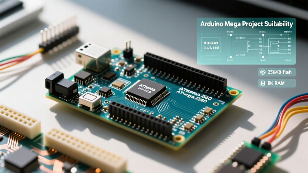
The ATmega2560 provides 256 KB of Flash memory (with 8 KB used by the bootloader), 8 KB of SRAM, and 4 KB of EEPROM. While 256 KB of Flash is generous for 8-bit systems, the 8 KB SRAM limit is the most frequent point of failure in advanced projects.
- Flash Memory (256 KB): Ideal for storing large lookup tables, complex state machines, and extensive firmware like Marlin for 3D printers. To preserve SRAM, always use the
F()macro to store static string literals in Flash (PROGMEM) rather than loading them into RAM at runtime. - SRAM (8 KB): This is your working memory for variables, stacks, and heaps. If you are building an audio processing node, a large LED matrix buffer, or a web server with heavy string manipulation, 8 KB will bottleneck your system. For context, a standard 60x60 WS2812B LED matrix requires nearly 10.8 KB of RAM just for the pixel buffer, making the Mega physically incapable of driving it natively without external DMA hardware.
- EEPROM (4 KB): Perfect for storing device configurations, calibration offsets, and boot counters that must survive power cycles. Rated for 100,000 write cycles, it should be used for infrequent saves rather than continuous data logging.
Project Suitability Matrix
How does the Mega stack up against other popular platforms for specific project categories? The following matrix breaks down suitability based on real-world engineering constraints.
| Project Category | Arduino Mega 2560 | Arduino Uno R4 | ESP32-S3 | Why the Mega Wins (or Loses) |
|---|---|---|---|---|
| Custom 3D Printer / CNC | Excellent | Poor | Good | Mega has native 5V stepper driver compatibility and massive shield ecosystem (RAMPS 1.4). |
| Multi-Sensor Serial Hub | Excellent | Poor | Good | 4 hardware UARTs allow simultaneous GPS, Cellular, and Debug streams without CPU-blocking SoftwareSerial. |
| High-Speed Data Acquisition | Poor | Good | Excellent | Mega's 10-bit ADC and 16 MHz clock limit sampling rates. ESP32 offers 12-bit ADC and dual-core processing. |
| IoT / Cloud Telemetry | Fair | Fair | Excellent | Mega lacks native WiFi/BT. Requires bulky ESP-01 or Ethernet shields, increasing BOM cost and power draw. |
Ideal Use Cases for the Arduino Mega
1. 3D Printing and CNC Motion Control
The Mega is the undisputed champion of open-source motion control. Firmware like Marlin relies heavily on the Mega's architecture. As noted in the Marlin Firmware Documentation, advanced features like auto-bed leveling (UBL), linear advance, and full-graphic LCD support easily consume over 150 KB of Flash and push SRAM limits. The Mega's abundance of digital pins perfectly maps to the RAMPS 1.4 and MKS Gen L shields, providing dedicated outputs for 5 stepper drivers, heated beds, multiple hotends, and endstops without needing complex I/O multiplexers.
2. Multi-Protocol Serial Gateways
If your project requires aggregating data from multiple serial devices—such as a NMEA GPS module, a PM2.5 air quality sensor, an RS485 industrial modem, and a USB debug console—the Mega's four hardware UARTs (Serial, Serial1, Serial2, Serial3) are invaluable. Unlike the Uno, which forces you to use the CPU-intensive and timing-prone SoftwareSerial library, the Mega handles simultaneous baud rates in hardware, preventing buffer overruns and dropped packets.
Hardware Edge Cases and Failure Modes
Experienced engineers know that dev boards have quirks that aren't always highlighted on the front page of the product listing. Here are the critical edge cases to design around when using the Mega.
The I2C Pinout Trap
A frequent mistake for developers migrating from the Uno to the Mega is assuming the I2C pins are located on A4 and A5. On the Mega, the dedicated I2C bus is routed to Pin 20 (SDA) and Pin 21 (SCL), as well as the dedicated header near the USB port. Furthermore, while the Mega has internal pull-up resistors on these lines, they are often too weak (typically 20kΩ to 50kΩ) for buses with high capacitance or long wire runs. Always add external 4.7kΩ pull-up resistors to the 5V rail when daisy-chaining multiple I2C sensors.
SPI Routing and the ICSP Header
On the Uno, the SPI bus is exposed on digital pins 11, 12, and 13. On the Mega, SPI is routed to pins 50 (MISO), 51 (MOSI), 52 (SCK), and 53 (SS). However, to maintain shield compatibility, the primary SPI access point on the Mega is the 2x3 ICSP header. If you are designing a custom PCB or wiring an SD card module directly, always reference the Microchip ATmega2560 Datasheet for the exact ICSP pinout to avoid conflicting with shields that use pins 50-53 for general I/O.
Power Delivery and Thermal Throttling
Expert Warning: Do not power high-current 5V peripherals directly from the Mega's onboard 5V pin if you are supplying more than 9V to the Vin jack or barrel connector.
The Mega utilizes a linear voltage regulator (typically an NCP1117ST50T3G or similar) to drop the Vin voltage down to 5V. Linear regulators dissipate excess voltage as heat. If you supply 12V to the board and draw 400mA from the 5V pin to power a relay module and an LCD, the regulator must dissipate (12V - 5V) * 0.4A = 2.8 Watts. The TO-223 package will rapidly exceed its thermal junction limit, triggering thermal shutdown and causing the board to reboot randomly. For any project drawing more than 150mA on the 5V rail, bypass the onboard regulator entirely by using an external LM2596 buck converter to supply 5V directly to the 5V pin (bypassing Vin).
Arduino Mega vs. ESP32: The 2026 Dilemma
Many makers default to the ESP32 for modern projects due to its low cost (~$6), dual-core 240 MHz processor, and native WiFi/Bluetooth. However, the ESP32 operates at 3.3V logic and has a limited number of GPIO pins that can be safely used for outputs (due to strapping pin restrictions and ADC2 conflicts with WiFi).
Choose the Arduino Mega when your project involves:
- Interfacing with legacy 5V TTL hardware, automotive relays, or standard NEMA stepper drivers (like A4988/DRV8825) without needing bidirectional logic level shifters.
- Running massive, established codebases like Marlin or GRBL-Mega that are deeply optimized for the AVR architecture.
- Requiring strict deterministic timing on a high number of pins without the interference of an RTOS or WiFi stack interrupting the main loop.
Conversely, choose the ESP32 if your project requires audio processing, camera interfaces, wireless telemetry, or high-speed analog sampling.
Frequently Asked Questions
Can I power the Arduino Mega directly via the 5V pin?
Yes, but with extreme caution. Supplying a regulated 5V source directly to the 5V pin bypasses the onboard voltage regulator and the USB polyfuse. Ensure your external power supply is strictly regulated; a voltage spike above 5.5V will instantly destroy the ATmega2560 chip and the 16U2 USB interface IC.
Why is my analogRead() fluctuating on unused pins?
The Mega features 16 analog inputs. Unconnected analog pins act as high-impedance antennas, picking up electromagnetic interference (EMI) from nearby digital traces or switching power supplies. Always tie unused analog pins to ground via a 10kΩ resistor, or configure them as digital outputs in your setup code to minimize ADC crosstalk.
Is the Arduino Mega suitable for battery-powered projects?
Out of the box, no. The onboard 16U2 USB chip, power LED, and voltage regulator draw a continuous idle current of roughly 30mA to 50mA. For low-power battery applications, you must physically modify the board (cutting the LED trace, removing the voltage regulator) and utilize the ATmega's native sleep modes, or pivot to a barebones ATmega2560 on a custom PCB.