
Why the Arduino Uno Datasheet R3 Matters for Beginners
When you first unbox an Arduino Uno R3, the included pamphlet barely scratches the surface of what the board can actually do. To unlock its true potential, troubleshoot hardware bugs, and design custom shields, you must learn to read the Arduino Uno datasheet R3. While the term 'datasheet' might sound intimidating to a beginner, it is simply the definitive instruction manual written by the engineers who designed the silicon and the printed circuit board (PCB).
In 2026, while newer platforms like the Uno R4 Minima and Wi-Fi variants dominate the market with 32-bit ARM Cortex-M4 processors, the classic 8-bit Uno R3 remains the undisputed king of legacy educational kits and reliable industrial prototyping. Priced at around $27.00 USD for the official board (with high-quality clones hovering near $14.00), understanding its hardware limitations is the difference between a project that runs for years and one that fries its voltage regulator in five minutes.
The 'Two Datasheets' Concept: Board vs. Silicon
The biggest misconception beginners have is that there is a single document called the 'Arduino Uno datasheet R3'. In reality, you are dealing with two distinct sets of documentation:
- The Board Schematic & Reference: Provided by Arduino, this covers the PCB layout, the USB-to-Serial converter, the voltage regulator, and the physical pin headers. You can find this on the official Arduino Uno Rev3 documentation page.
- The Microcontroller Datasheet: Provided by Microchip (formerly Atmel), this 400+ page PDF details the ATmega328P chip itself, including its internal registers, timers, and memory architecture. You can download the official ATmega328P datasheet from Microchip.
Decoding the ATmega328P: The Brain of the Uno R3
The heart of the Uno R3 is the ATmega328P-PU microcontroller, housed in a 28-pin DIP (Dual In-line Package) socket. Because it is socketed, you can easily replace it if you accidentally short-circuit and fry the chip—a massive advantage over surface-mount alternatives. Here are the critical specifications you need to memorize or keep on your workbench cheat sheet:
| Specification | ATmega328P Value | Practical Meaning for DIYers |
|---|---|---|
| Architecture | 8-bit AVR RISC | Processes data in 8-bit chunks; ideal for simple logic, not heavy math. |
| Clock Speed | 16 MHz | Executes roughly 16 million instructions per second. |
| Flash Memory | 32 KB (0.5 KB used by bootloader) | Where your compiled sketch lives. Limits complex code or large lookup tables. |
| SRAM | 2 KB | Volatile memory for variables. Running out of SRAM causes random crashes. |
| EEPROM | 1 KB | Non-volatile storage for saving settings when power is lost. |
| Operating Voltage | 5V Logic | Requires logic level shifters to interface with modern 3.3V I2C/SPI sensors. |
Power Supply Constraints & Thermal Failure Modes
If there is one section of the Arduino Uno R3 schematic that beginners ignore, it is the power architecture. The board features multiple ways to receive power, but they are not created equal. The barrel jack and the 'Vin' pin route through an NCP1117ST50T3G linear voltage regulator, which steps down unregulated voltage to a clean 5V.
The Thermal Shutdown Trap
Linear regulators work by burning off excess voltage as heat. The recommended input voltage via the barrel jack is 7V to 12V. Let us look at a real-world failure scenario: You connect a 12V DC wall adapter to the barrel jack and draw 400mA from the 5V pin to power a strip of WS2812B addressable LEDs. The NCP1117 must dissipate the voltage difference as heat.
The Math: (12V Input - 5V Output) × 0.4A Current = 2.8 Watts of heat.
The SOT-223 surface-mount package on the Uno R3 lacks a dedicated heatsink. At 2.8W, the junction temperature will rapidly exceed 150°C, triggering the chip's internal thermal protection. Your Arduino will randomly reboot, and the LEDs will flicker. The Fix: If you need to draw more than 200mA from the 5V pin, bypass the onboard regulator entirely. Power the board via the USB port (which can supply up to 500mA safely) or use a dedicated 5V switching buck converter wired directly to the '5V' header pin.
Navigating the Pinout: Beyond Digital and Analog
When reading the board's pinout diagram, beginners often see only 'Digital 0-13' and 'Analog A0-A5'. However, the datasheet reveals hidden multiplexed functions that are critical for advanced projects:
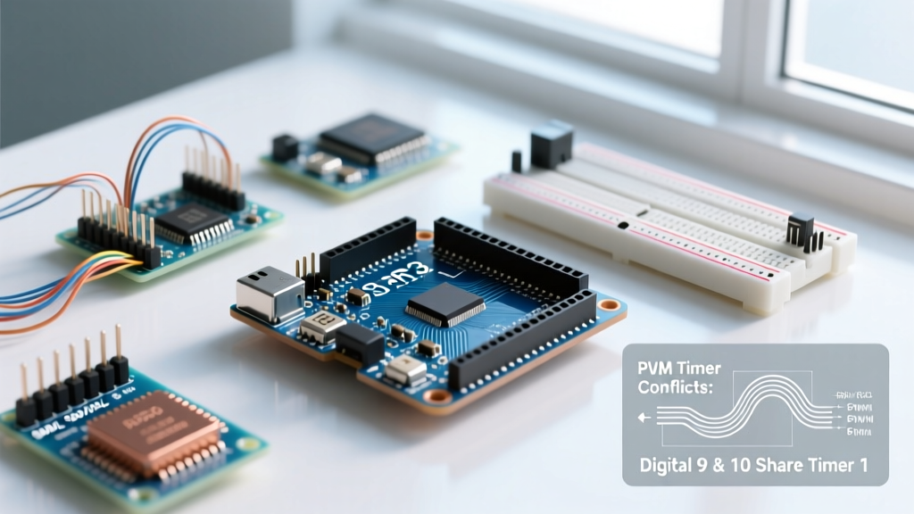
- PWM (Pulse Width Modulation): Only pins 3, 5, 6, 9, 10, and 11 support hardware PWM (marked with a ~ on the silkscreen). These are driven by the ATmega328P's internal hardware timers, allowing for smooth LED fading and motor control without blocking your code.
- I2C Bus: The dedicated SDA (A4) and SCL (A5) pins are internally wired to the same lines as the separate 6-pin header near the USB port. This was a major revision in the R3 design to support modern shields.
- SPI Bus: Pins 11 (MOSI), 12 (MISO), and 13 (SCK) are shared with the ICSP (In-Circuit Serial Programming) header. If you are using an SPI-based display, you cannot use pins 11-13 for general digital I/O simultaneously.
- Pin Change Interrupts (PCINT): Unlike the dedicated hardware interrupts on pins 2 and 3 (INT0 and INT1), the datasheet shows that almost all other pins support Pin Change Interrupts, allowing you to wake the microcontroller from sleep mode or read rotary encoders on any digital pin.
Analog-to-Digital Converter (ADC) Nuances
The Uno R3 features a 10-bit ADC, meaning it maps input voltages between 0 and 5V into integer values between 0 and 1023. This yields a resolution of roughly 4.88mV per step (5V / 1024). However, the Microchip datasheet highlights a powerful, often-ignored feature: the Internal 1.1V Reference.
By default, the ADC uses the 5V rail as its reference. If your 5V rail fluctuates (common when powered via USB from a noisy PC port), your analog sensor readings will drift. By adding analogReference(INTERNAL); to your sketch, you force the ADC to use a highly stable internal 1.1V bandgap reference. This is mandatory when reading low-voltage sensors like thermistors or current shunts where precision matters more than range.
The ATmega16U2: The Hidden Second Processor
Many beginners believe the Uno uses an FTDI chip for USB communication. Older models like the Duemilanove did, but the Uno R3 schematic reveals a second microcontroller: the ATmega16U2. This chip acts as a USB-to-Serial bridge, translating USB data from your PC into UART TX/RX signals for the main ATmega328P.
Because the 16U2 is a fully programmable AVR chip in its own right, you can reflash its firmware using the DFU (Device Firmware Upgrade) protocol. Hobbyists frequently overwrite the serial bridge firmware with LUFA-based HID firmware, turning the Arduino Uno R3 into a native USB keyboard, mouse, or MIDI controller without needing any additional hardware.
How to Find Information in the 400-Page Microchip PDF
Opening the ATmega328P datasheet for the first time is overwhelming. Here is a professional workflow for extracting what you need:
- Skip the Electrical Characteristics (for now): Pages of graphs showing voltage vs. temperature are useful for aerospace engineering, but not for blinking an LED.
- Go Straight to 'Register Descriptions': If you want to bypass the slow
digitalWrite()function in the Arduino IDE, look up thePORTB,DDRB, andPINBregisters. This allows you to manipulate pins 8 through 13 in a single clock cycle using direct port manipulation (e.g.,PORTB |= (1 << 5);to set pin 13 HIGH instantly). - Check the 'Timers/Counters' Section: If you are building a frequency generator or reading RC receiver PPM signals, the Timer1 and Timer2 sections will show you exactly how to configure the prescalers and compare match registers.
Common Beginner Mistakes When Ignoring the Datasheet
Failing to consult the Arduino Uno datasheet R3 leads to predictable, often destructive hardware failures. Avoid these common pitfalls:
- Backfeeding 5V into the Vin Pin: The Vin pin is connected to the input of the NCP1117 regulator. Supplying 5V to Vin will result in an output of roughly 3.8V at the 5V header due to the regulator's dropout voltage. Always feed regulated 5V directly into the '5V' pin.
- Exceeding the 20mA Pin Limit: The absolute maximum DC current per I/O pin is 40mA, but the recommended operating condition is 20mA. Connecting a standard 5V relay module directly to a digital pin without a transistor will pull 70mA+, permanently damaging the ATmega328P's internal silicon traces.
- Forgetting I2C Pull-up Resistors: The Uno R3 schematic shows that the board does not include internal pull-up resistors on the SDA and SCL lines. If your breakout board lacks them, your I2C bus will float, resulting in failed
Wire.begin()scans.
Frequently Asked Questions
Can I power the Arduino Uno R3 with a 9V battery?
Yes, via the barrel jack or Vin pin. However, standard 9V alkaline batteries have a low current capacity (around 500mAh) and high internal resistance. They are fine for low-power sensor logging, but will cause brownouts if you attempt to drive motors or high-brightness LEDs.
Is the Arduino Uno R3 still worth buying in 2026?
Absolutely. While the official Arduino Uno R3 lacks native wireless connectivity and operates at 5V logic, its massive library support, rugged DIP-socketed design, and 5V tolerance make it the most forgiving board for beginners learning electronics fundamentals.