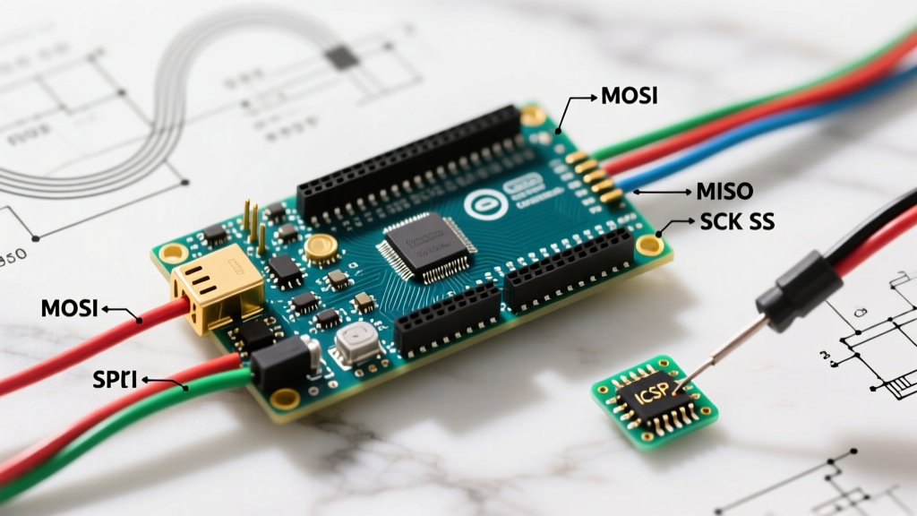

The Definitive Guide to Arduino Mega SPI Pins
When scaling up from a simple sensor read to a complex, multi-peripheral data logger, the Serial Peripheral Interface (SPI) becomes the critical bottleneck in your design. The Arduino Mega 2560, powered by the ATmega2560 microcontroller, offers massive I/O expansion and abundant memory, but its SPI implementation harbors specific routing quirks that routinely trap beginners and intermediate makers alike. Whether you are driving an ILI9341 TFT display, logging high-frequency data to a W25Q128 flash chip, or networking via a W5500 Ethernet module, understanding the exact hardware routing of the Arduino Mega SPI pins is non-negotiable for signal integrity and bus stability.
The Digital Pin Trap: Why Pins 11, 12, and 13 Fail
The most common failure mode when migrating a project from an Arduino Uno to an Arduino Mega is the assumption that the SPI bus remains on digital pins 11 (MOSI), 12 (MISO), and 13 (SCK). On the Mega, these pins are strictly general-purpose I/O and are not routed to the hardware SPI peripheral. Attempting to use them with the standard SPI.h library will result in silent failures or bit-banged software SPI that maxes out at a few kilohertz, entirely defeating the purpose of hardware acceleration.
Exact Hardware SPI Pinout (Digital Headers)
On the Arduino Mega 2560 Rev3, the hardware SPI bus is mapped to the following digital pins, located on the far right side of the primary digital header:
- Pin 50 (MISO): Master In, Slave Out. The Mega receives data from the peripheral.
- Pin 51 (MOSI): Master Out, Slave In. The Mega sends data to the peripheral.
- Pin 52 (SCK): Serial Clock. Generated by the Mega to synchronize data transfer.
- Pin 53 (SS): Slave Select. Critical Edge Case: On the ATmega2560, if Pin 53 is configured as an INPUT and is pulled LOW, the SPI controller automatically aborts Master mode and switches to Slave mode, instantly corrupting your bus. Pin 53 must always be configured as an OUTPUT or kept HIGH, even if you are using different pins for your peripheral Chip Select (CS) lines.
The ICSP Header: Your Best Friend for Cross-Board Compatibility
While pins 50-53 are functional, relying on them makes your code and wiring rigidly tied to the Mega. The superior method for wiring SPI peripherals on any AVR-based Arduino is the 2x3 ICSP (In-Circuit Serial Programming) header. Located near the USB port, this header exposes the SPI bus directly from the microcontroller, bypassing the digital pin mapping entirely.
Pro-Tip for Shield Design: If you are designing a custom PCB shield or wiring a permanent installation, always route SPI traces to the ICSP header footprint. This ensures your hardware will work identically on an Uno, Nano, and Mega without requiring jumper wire modifications. For comprehensive board schematics, refer to the official Arduino Mega 2560 documentation.
ICSP Header Pinout (Looking down at the board, USB facing left)
- Pin 1 (MISO): Top-left
- Pin 2 (5V VCC): Top-middle
- Pin 3 (SCK): Top-right
- Pin 4 (MOSI): Bottom-left
- Pin 5 (RESET): Bottom-middle
- Pin 6 (GND): Bottom-right
Board Comparison: Mega vs. Uno vs. ESP32 for SPI Heavy Loads
How does the Mega stack up against other popular platforms when managing multiple high-speed SPI devices? Below is a technical comparison matrix evaluating native SPI capabilities, logic levels, and bus expansion limits.
| Feature | Arduino Mega 2560 | Arduino Uno R3 | ESP32 (Standard DevKit) |
|---|---|---|---|
| Native SPI Buses | 1 (Hardware) + MSPIM workarounds | 1 (Hardware) | 2 to 4 (Hardware via SPI, HSPI, VSPI) |
| Max Clock Speed | 8 MHz (F_CPU / 2) | 8 MHz (F_CPU / 2) | 80 MHz (APB Clock dependent) |
| Logic Level | 5V (Requires level shifting for 3.3V sensors) | 5V (Requires level shifting) | 3.3V (Native for modern sensors) |
| SS Pin Hardware Override | Yes (Pin 53 forces Slave mode if LOW) | Yes (Pin 10 forces Slave mode if LOW) | No (CS pins are fully software-managed) |
| Typical 2026 Pricing | $45 (Official) / $15 (Clone) | $27 (Official) / $12 (Clone) | $8 - $12 (Third-party DevKits) |
Signal Integrity: 5V Logic vs. 3.3V Peripherals
The Arduino Mega operates at 5V logic. However, 95% of modern high-speed SPI peripherals—including BME280 environmental sensors, RC522 RFID readers, and modern TFT displays—operate at 3.3V and are not 5V tolerant. Feeding 5V into the MISO or SCK pins of a 3.3V module will degrade the silicon over time or cause immediate catastrophic failure.
Choosing the Right Level Shifter
To safely interface the Mega's SPI pins with 3.3V devices, you must use a logic level converter. However, not all converters are created equal when dealing with high-frequency SPI clocks:
- BSS138 MOSFET-based Shifters: These cheap, ubiquitous breakout boards (usually $1-$2) rely on pull-up resistors and parasitic gate capacitance. They are fine for I2C (400 kHz) but will severely distort SPI square waves above 2 MHz, leading to data corruption on TFT screens.
- SN74LVC1T45 / SN74LVCH8T245 ICs: For reliable 8 MHz SPI operation on the Mega, you must use dedicated push-pull logic level translation ICs. These maintain sharp rise and fall times, ensuring the setup and hold times required by the Arduino SPI communication protocols are strictly met.
Advanced Edge Case: Adding a Second SPI Bus via MSPIM
A major limitation of the Arduino Mega is having only one dedicated hardware SPI bus. If you are sharing the bus between an SD card and an Ethernet module, you must carefully manage Chip Select (CS) pins and use SPI.beginTransaction() to prevent bus collisions. But what if you need a completely independent second SPI bus to drive a secondary display without slowing down your data logging?
The ATmega2560 features four USART (Universal Synchronous and Asynchronous Receiver-Transmitter) modules. By configuring one of these USARTs in MSPIM (Master SPI Mode), you can create a second, fully hardware-accelerated SPI bus. This is an advanced technique documented in the SparkFun SPI tutorial and the official Microchip ATmega2560 datasheet. Utilizing USART1 (Pins 18/TX1 and 19/RX1) in MSPIM mode allows you to offload a secondary TFT display, freeing the primary SPI bus (Pins 50-52) exclusively for high-speed SD card logging.
Real-World Troubleshooting & Failure Modes
When deploying the Mega in the field, keep these specific failure modes in mind:
- Parasitic Capacitance on Breadboards: Long jumper wires and breadboard tracks add capacitance to the SCK and MOSI lines. If your SPI bus drops out when wires exceed 15cm, lower the SPI clock divider in your code (e.g., from
SPI_CLOCK_DIV2toSPI_CLOCK_DIV4) to give the signal more time to settle. - Missing Pull-up Resistors on CS Lines: When the Mega resets or boots, its GPIO pins float before the bootloader initializes. This can cause SPI peripherals (like SD cards) to enter an undefined state. Always place a 10kΩ pull-up resistor on every peripheral's Chip Select line to ensure they remain deselected during the Mega's boot sequence.
- Clone Board Trace Routing: While high-quality Mega clones (using the CH340G USB-UART bridge) replicate the schematic perfectly, some ultra-cheap variants route the ICSP header traces with sharp 90-degree angles and missing ground planes. For high-speed SPI, stick to official boards or reputable clone manufacturers to maintain controlled impedance.
Final Verdict
The Arduino Mega 2560 remains a powerhouse for complex, multi-sensor DIY projects in 2026, provided you respect its hardware routing rules. By abandoning the digital pin 11-13 habit, utilizing the ICSP header for universal compatibility, and implementing proper 3.3V level shifting, you can push the ATmega2560's SPI bus to its maximum 8 MHz potential without data corruption. For projects requiring multiple independent high-speed buses, consider leveraging the MSPIM USART workaround before abandoning the AVR ecosystem for an ESP32.