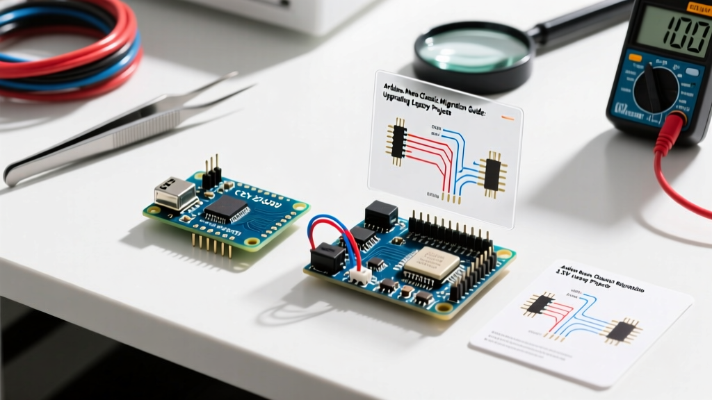

The Architecture Shift: Why Pinout Migration Matters
Migrating a legacy project from a classic 5V ATmega328P-based Arduino Nano to the Arduino Nano 33 IoT is not a simple drop-in replacement. While the physical footprint (18x2 pins, 0.6-inch width) remains identical, the underlying silicon represents a massive architectural leap. The Nano 33 IoT is powered by a 32-bit ARM Cortex-M0+ SAMD21G18A microcontroller running at 48MHz, paired with a u-blox NINA-W102 Wi-Fi/Bluetooth module and an ATECC608A cryptographic co-processor.
For hardware engineers and advanced makers in 2026, understanding the Arduino Nano 33 IoT pinout is critical to avoiding catastrophic GPIO failure. The most common migration failure occurs when developers assume the new board's I/O pins are 5V tolerant. They are not. Applying 5V logic directly to the SAMD21's pins will permanently destroy the silicon. This guide provides a deep-dive technical roadmap for adapting your legacy shields, sensors, and actuators to the Nano 33 IoT's 3.3V ecosystem.
⚠️ Critical Migration Warning: Unlike the classic Nano, no GPIO pins on the Nano 33 IoT are 5V tolerant. The absolute maximum rating for any I/O pin is 3.6V. Always use bidirectional logic level shifters when interfacing with 5V legacy shields.Complete Arduino Nano 33 IoT Pinout Breakdown
To successfully migrate your platform, you must map your legacy connections to the SAMD21's alternate functions. Below is the definitive mapping table comparing the classic 5V Nano to the Nano 33 IoT.
| Pin Label | Classic Nano (ATmega328P) | Nano 33 IoT (SAMD21) | Migration Notes |
|---|---|---|---|
| VIN | 7V - 12V (Recommended) | 5V - 21V (MPM3610 Buck) | Do not feed 12V if using cheap clone shields with poor thermal dissipation; stick to 5V-7V. |
| 5V Pin | Regulated 5V Output | VUSB (5V from USB only) | If powered via VIN, the 5V pin outputs NOTHING unless the VUSB jumper is bridged. |
| 3V3 Pin | 150mA max (LDO) | Up to 1A (Buck Converter) | Massive upgrade. Can power external 3.3V sensors and LTE modules directly. |
| A4 (SDA) / A5 (SCL) | I2C (5V Logic) | I2C (3.3V Logic) | Requires level shifting if shield has 5V pull-ups. |
| D11, D12, D13 | SPI (5V Logic) | SPI (3.3V Logic) | External SPI bus. NINA-W102 uses an internal SPI bus. |
| A0 - A7 | 10-bit ADC (5V Ref) | 12-bit ADC (3.3V Ref) | Max analog input is 3.3V. Use voltage dividers for 5V+ signals. |
Step-by-Step Migration: Adapting Legacy 5V Shields
When migrating a legacy shield (like the classic Adafruit Motor Shield V1 or older 5V LCD displays), you must address both voltage translation and I2C pull-up conflicts. According to SparkFun's Logic Levels guide, mixing 3.3V and 5V logic without translation will result in degraded signal integrity or immediate silicon latch-up.
1. Solving the I2C Pull-Up Resistor Conflict
Most legacy 5V I2C shields feature 4.7kΩ pull-up resistors tied directly to the 5V rail. If you plug this shield into the Nano 33 IoT, the SDA and SCL lines (A4 and A5) will be pulled up to 5V, bypassing the board's 3.3V regulator and feeding 5V directly into the SAMD21's GPIO pins.
- Sever the 5V Pull-Up Trace: Use an X-Acto knife to cut the trace connecting the shield's pull-up resistors to the 5V plane.
- Insert a BSS138 Level Shifter: Wire a BSS138 N-channel MOSFET bidirectional level shifter between the Nano 33 IoT and the shield.
- Configure Pull-Ups: Connect 2.2kΩ pull-up resistors on the low-voltage (LV) side to the Nano's 3.3V pin, and 4.7kΩ pull-ups on the high-voltage (HV) side to the shield's 5V rail.
2. Translating UART and SPI Lines
For high-speed unidirectional or bidirectional buses like SPI (D11-D13) or UART (TX/RX), MOSFET-based shifters often fail due to gate capacitance limiting bandwidth. Instead, use a dedicated IC like the Texas Instruments TXB0104 (4-bit bi-directional) or SN74LVC8T245 (8-bit). These ICs support data rates up to 100Mbps, ensuring your SPI displays and SD card modules do not experience timing glitches during migration.
Analog-to-Digital (ADC) Edge Cases and Math
The SAMD21 microcontroller features a true 12-bit ADC, offering 4096 discrete steps compared to the ATmega328P's 10-bit (1024 steps). However, to maintain backward compatibility with legacy code, the Arduino core defaults the `analogReadResolution()` to 10 bits.
Expert Tip: If you are migrating precision sensor code (e.g., load cells or thermistors), explicitly callanalogReadResolution(12);in yoursetup()loop. This reduces quantization noise and provides a much smoother data curve for PID control loops.
Migration Math: If your legacy code calculates voltage using the 5V reference, it likely looks like this:
float voltage = sensorVal * (5.0 / 1023.0);
You must update this to reflect the 3.3V reference and 12-bit resolution:
float voltage = sensorVal * (3.3 / 4095.0);
Furthermore, ensure your analog sensor's maximum output does not exceed 3.3V. If you are reading a 5V analog pressure transducer, you must build a precision voltage divider using 1% tolerance resistors (e.g., 10kΩ and 20kΩ) to scale the 0-5V signal down to 0-3.3V.
Navigating Internal NINA-W102 Pin Conflicts
A unique aspect of the Arduino Nano 33 IoT architecture is the integration of the u-blox NINA-W102 Wi-Fi/Bluetooth module. The NINA module is essentially an ESP32 that communicates with the main SAMD21 chip via an internal SPI bus.
When reviewing the official Nano 33 IoT cheat sheet, you will notice that several pins are reserved for internal routing. While the external SPI pins (D11, D12, D13) are broken out to the headers, the chip select (CS) and handshake pins for the Wi-Fi module are tied to internal SAMD21 pins (like D24, D25, D26, D27). Do not attempt to use digital pins 24 through 27 for external peripherals, as toggling these pins in your sketch will crash the Wi-Fi stack or cause the NINA module to reset unexpectedly.
Firmware and Library Migration Gotchas
Hardware pinout is only half the battle. Platform migration requires updating your software dependencies to match the ARM Cortex-M0+ architecture.
- Wi-Fi Libraries: Replace
ESP8266WiFi.horWiFi.h(AVR) withWiFiNINA.h. The API is similar, but the underlying socket management is handled by the NINA module's firmware, requiring you to occasionally update the NINA firmware via the Arduino IDE's 'WiFi101 / WiFiNINA Firmware Updater' tool. - Interrupts: The SAMD21 handles external interrupts differently. While
attachInterrupt(digitalPinToInterrupt(pin), ISR, mode)still works, the SAMD21 supports interrupts on almost all GPIO pins, not just D2 and D3 like the classic Nano. However, ISR execution times are faster, so ensure your debounce logic is calibrated for a 48MHz clock. - Crypto Integration: The onboard ATECC608A secure element is a massive advantage for 2026 IoT security standards. Use the
ArduinoECCX08library to generate hardware-backed X.509 certificates for AWS IoT or Azure DPS, eliminating the need to store private keys in your sketch's flash memory.
Cost and BOM Analysis for 2026 Migration
Migrating a fleet of prototype devices from the classic Nano to the Nano 33 IoT impacts your Bill of Materials (BOM). Below is a realistic cost breakdown for a single-node IoT sensor migration in 2026.
| Component | Classic 5V Node | Nano 33 IoT Node |
|---|---|---|
| Microcontroller Board | $5.00 (Clone) / $24.00 (Official) | $21.50 (Official) |
| Wi-Fi Module (e.g., ESP-01S) | $3.50 + Wiring | Included (NINA-W102) |
| Logic Level Shifters (x2) | $0.00 (Not Needed) | $2.50 (BSS138 Breakouts) |
| Crypto / Security IC | $1.50 (External I2C) | Included (ATECC608A) |
| Total Estimated BOM | $10.00 - $29.00 | $24.00 |
While the upfront cost of the Nano 33 IoT is higher than a clone classic Nano, the integration of Wi-Fi, Bluetooth LE, and hardware cryptography drastically reduces PCB footprint, assembly time, and external component sourcing. By carefully managing the 3.3V logic translation and updating your ADC math, the Nano 33 IoT serves as an incredibly robust, future-proof platform for modern edge-computing and IoT deployments.