
The Architecture Divide: ATmega328P vs. Renesas RA4M1
When evaluating interrupt pins on Arduino Uno for real-time project suitability, the first critical step is identifying your board revision. In 2026, the Arduino Uno ecosystem is split between the legacy Uno R3 and the modern Uno R4 (Minima and WiFi). This hardware distinction fundamentally alters how you approach external interrupts.
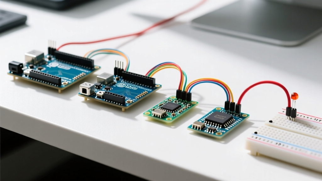
The classic Uno R3 relies on the Microchip ATmega328P microcontroller, which features exactly two dedicated external interrupt pins: INT0 (Digital Pin 2) and INT1 (Digital Pin 3). Conversely, the Uno R4 utilizes the 32-bit Renesas RA4M1 ARM Cortex-M4 processor, which supports external interrupts on almost all digital and analog pins. Understanding this divide is the cornerstone of project suitability analysis, as it dictates whether you must rely on complex Pin Change Interrupts (PCINT) or if you have the luxury of ubiquitous hardware interrupt vectors.
Hardware Mapping and Electrical Characteristics
Before wiring sensors, you must map the logical pins to their underlying hardware registers. On the ATmega328P, external interrupts are controlled via the External Interrupt Control Register A (EICRA) and the External Interrupt Mask Register (EIMSK). The Arduino IDE abstracts this via the attachInterrupt() function, but knowing the hardware limits prevents edge-case failures.
| Board Model | MCU Core | Dedicated INT Pins | PCINT Support | Max GPIO Interrupts | Typical Price (2026) |
|---|---|---|---|---|---|
| Uno R3 | ATmega328P (8-bit AVR) | D2 (INT0), D3 (INT1) | Yes (PCMSK0/1/2) | 2 (Hardware) + 23 (PCINT) | $27.00 |
| Uno R4 Minima | Renesas RA4M1 (ARM M4) | D0-D13, A0-A5 | N/A (Native support) | Up to 20+ | $20.00 |
| Uno R4 WiFi | RA4M1 + ESP32-S3 | D0-D13, A0-A5 | N/A (Native support) | Up to 20+ | $27.50 |
Project Suitability Matrix: When to Use INT0/INT1
Not every sensor or input warrants an interrupt. Using interrupts for slow-changing signals wastes CPU context-switching overhead and introduces debounce complexities. Below is a suitability analysis for common project types when using the Uno R3's dedicated pins (D2 and D3).
1. Rotary Encoders and Quadrature Decoding
Suitability: High (with caveats)
Optical or magnetic rotary encoders output high-frequency quadrature signals. At 1000 RPM with a 600 PPR (Pulses Per Revolution) encoder, you generate 12,000 state changes per second. Polling will miss steps. You must use interrupts. However, a single encoder requires two pins. On the Uno R3, you would assign one channel to D2 (INT0) and rely on a Pin Change Interrupt (PCINT) for the second channel, or use the R4 to assign both to dedicated hardware interrupts.
2. Flow Sensors and Anemometers
Suitability: Excellent
Hall-effect flow sensors (like the YF-S201) output a clean square wave proportional to fluid velocity. Because the signal is relatively low frequency (typically 10Hz to 200Hz) and the pulse width is wide, D2 or D3 is perfectly suited. The ISR (Interrupt Service Routine) simply increments a volatile counter, leaving the main loop free to handle Wi-Fi transmissions or display updates.
3. Tactile Buttons and Mechanical Switches
Suitability: Poor
Mechanical switches suffer from contact bounce, generating microsecond-level noise that can trigger an ISR dozens of times per press. While software debouncing inside an ISR is possible (using millis() checks), it is generally considered bad practice. For buttons, timer-based polling (checking state every 20ms) or dedicated PCINTs with hardware RC filters are vastly superior architectures.
ISR Timing, Overhead, and Edge Cases
A common failure mode in real-time projects is ISR bloat. When an interrupt triggers on the 16MHz ATmega328P, the CPU halts the main loop, pushes the program counter to the stack, and jumps to the vector. According to Nick Gammon's definitive analysis of AVR interrupts, the context-switching overhead alone consumes roughly 5.125 µs. If you use the Arduino attachInterrupt() wrapper, add another 2-3 µs of C++ function call overhead.
Expert Rule of Thumb: Your ISR should execute in under 10 µs. Never use
delay(),Serial.print(), or I2C/SPI transactions inside an ISR. If your I2C sensor (like an MPU6050 IMU) requires 400 µs to read a FIFO buffer, an ISR will cause a system lockup because the Wire library relies on interrupts that are globally disabled during your ISR execution.
The Volatile Keyword and Atomic Operations
When sharing data between the ISR and the main loop, variables must be declared as volatile. Furthermore, when reading multi-byte variables (like a 16-bit integer or 32-bit long) in the main loop, you must temporarily disable interrupts to prevent data tearing—where the ISR updates the high byte while the main loop reads the low byte.
noInterrupts();
long safeCopy = pulseCount;
interrupts();
Hardware Mitigations: EMI and Signal Integrity
In industrial or robotics projects, electrical noise is the enemy of interrupt pins. Stepper motor drivers (like the TI DRV8825 or Allegro A4988) and brushed DC motors generate massive Electromagnetic Interference (EMI). This noise can couple into long unshielded wires connected to D2 or D3, causing phantom interrupt triggers.
Designing the Hardware Filter
Do not rely solely on software debouncing for noisy environments. Implement a hardware low-pass RC filter combined with a Schmitt trigger.
- Basic RC Filter: A 10kΩ series resistor and a 100nF ceramic capacitor to ground yields a cutoff frequency of ~159 Hz. This is excellent for mechanical limit switches but will distort high-speed encoder signals.
- Schmitt Trigger (74HC14): For high-frequency signals in noisy environments, pass the sensor output through a hex inverting Schmitt trigger IC. This provides strict hysteresis (typically 0.9V at 5V VCC), ensuring that EMI spikes below the threshold are entirely ignored by the ATmega328P.
- Internal Pull-ups: Always enable the internal 20kΩ-50kΩ pull-up resistors via
pinMode(pin, INPUT_PULLUP)if your sensor uses open-drain outputs (like many Hall-effect sensors). Leaving a pin floating guarantees erratic interrupt behavior.
Expanding Limits: Pin Change Interrupts (PCINT)
If your Uno R3 project requires more than two interrupt-capable sensors (e.g., a robot with four wheel encoders and a collision bumper), you must utilize Pin Change Interrupts. The ATmega328P groups its I/O pins into three PCINT vectors (PCINT0, PCINT1, PCINT2).
The limitation of PCINT is that it only triggers on any logic change (rising or falling), and it does not tell you which pin in the port triggered it. Your ISR must manually read the entire port register (e.g., PINB) and XOR it with the previous state to identify the culprit. While libraries like EnableInterrupt abstract this, they add significant overhead. For projects requiring more than 4 high-speed interrupt sources, migrating to the Uno R4 or an ESP32 is the most architecturally sound decision.
Frequently Asked Questions
Can I use analog pins as interrupts on the Uno R3?
Yes, but only as Pin Change Interrupts (PCINT). Analog pins A0-A5 map to PCINT8-PCINT13 (PCMSK1 register). They do not support the dedicated INT0/INT1 hardware vectors, meaning you cannot use attachInterrupt() with them natively without a PCINT library.
Why is my encoder missing steps at high RPM?
If you are using the Uno R3, the 16MHz clock speed and ISR overhead limit reliable quadrature decoding to roughly 15,000-20,000 edges per second. Beyond this, the CPU spends 100% of its time inside the ISR, starving the main loop. For high-RPM motor control, offload quadrature decoding to a dedicated hardware encoder IC (like the LS7366R) or upgrade to the Uno R4.
Does the 'RISING' or 'FALLING' trigger mode affect latency?
No. The trigger mode is configured in the EICRA register and evaluated asynchronously by the hardware. The latency from the physical edge to the ISR execution remains constant regardless of whether you select RISING, FALLING, or CHANGE.