
Why Choose the Arduino Mega 2560 Rev3 for Complex Builds?
When your project outgrows the 14 digital I/O pins of the standard Uno, the Arduino Mega 2560 Rev3 is the definitive upgrade path. Offering 54 digital I/O pins, 16 analog inputs, and four hardware UARTs (serial ports), it is the workhorse of the DIY electronics and prototyping community. As of 2026, a genuine Arduino Mega 2560 Rev3 retails for approximately $48 to $52, while third-party clones utilizing the CH340 USB-to-serial chip can be sourced for $12 to $16.
This guide walks you through the exact setup process, highlights the critical hardware changes specific to the Rev3 iteration, and provides a complete first-project tutorial to leverage its dedicated I2C bus.
Verifying Your Rev3 Hardware Architecture
Before plugging in your board, it is crucial to verify that you actually have a Revision 3 board, as older revisions (Rev1 and Rev2) have different pin mappings and USB interfaces. According to the Arduino Official Mega 2560 Rev3 Documentation, the Rev3 introduced three major hardware changes:
- USB-to-Serial Chip: The Rev3 uses the ATmega16U2-MU instead of the older 8U2. This allows for faster transfer rates and more stable USB connectivity on modern Windows 11 and macOS environments.
- IOREF Pin: A new pin located near the reset button provides the voltage reference (5V) that shields use to configure their logic level circuitry.
- Dedicated I2C Header: The SDA and SCL pins were moved to dedicated pins (20 and 21) right next to the AREF pin, ensuring compatibility with all R3-form-factor shields. On older revisions, I2C was exclusively tied to Analog pins A4 and A5.
IDE Configuration and Driver Setup (2026 Edition)
To program the Arduino Mega 2560 Rev3, you will need the latest Arduino IDE (version 2.3.x or newer). Follow these precise steps to ensure your environment recognizes the board's ATmega2560 microcontroller:
- Download and install the Arduino IDE from the official Arduino software portal.
- Connect the Mega to your PC using a high-quality USB-B to USB-A (or USB-C) cable. Warning: Many cheap cables are charge-only and lack the D+/D- data lines required for serial communication.
- Open the IDE, navigate to Tools > Board > Arduino AVR Boards, and select Arduino Mega or Mega 2560.
- Under Tools > Processor, ensure ATmega2560 (Mega 2560) is selected.
- Select the correct COM port under Tools > Port. If the port is greyed out on a Windows machine and you are using a clone board, you must download and install the CH340/CH341 driver from the WCH official website.
First Project: I2C Multi-Sensor Environmental Hub
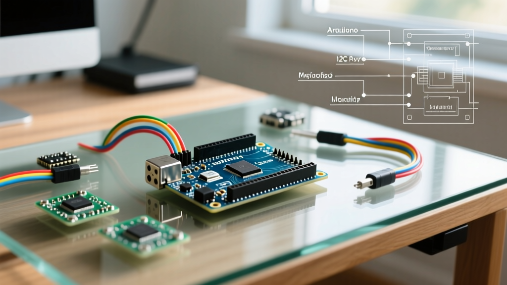
To demonstrate the Mega's capabilities, we will build an environmental monitor using a BME280 sensor (measuring temperature, humidity, and barometric pressure) and a 16x2 I2C LCD. This project specifically utilizes the Mega's dedicated hardware I2C pins (20 and 21), freeing up the analog pins for other uses.
Component List and Wiring Matrix
For this build, ensure your BME280 module has an onboard 3.3V voltage regulator and logic level shifters if you are powering it from the Mega's 5V rail. The Adafruit BME280 Breakout Guide provides excellent schematics for 5V-tolerant wiring.
| Arduino Mega 2560 Rev3 Pin | Component | Component Pin | Notes |
|---|---|---|---|
| 5V | BME280 Module | VIN / VCC | Use 5V only if module has onboard regulator |
| GND | BME280 Module | GND | Common ground required |
| Pin 20 (SDA) | BME280 Module | SDI / SDA | Dedicated Rev3 I2C data line |
| Pin 21 (SCL) | BME280 Module | SCK / SCL | Dedicated Rev3 I2C clock line |
| 5V | 16x2 I2C LCD | VCC | Standard 5V logic |
| GND | 16x2 I2C LCD | GND | Common ground required |
| Pin 20 (SDA) | 16x2 I2C LCD | SDA | Shared I2C bus (different address) |
| Pin 21 (SCL) | 16x2 I2C LCD | SCL | Shared I2C bus |
The C++ Implementation
Before uploading, install the Adafruit BME280 Library and the LiquidCrystal I2C library via the Arduino Library Manager. The code below initializes the I2C bus at 400kHz (Fast Mode), which the ATmega2560 natively supports, ensuring rapid sensor polling without blocking the main loop.
#include <Wire.h>
#include <Adafruit_BME280.h>
#include <LiquidCrystal_I2C.h>

Adafruit_BME280 bme;
LiquidCrystal_I2C lcd(0x27, 16, 2); // Default I2C address for most LCD backpacks

void setup() {
  Serial.begin(115200);
  Wire.begin();
  Wire.setClock(400000); // Enable 400kHz I2C Fast Mode

  lcd.init();
  lcd.backlight();

  if (!bme.begin(0x76)) { // BME280 I2C address (0x76 or 0x77)
    Serial.println("Could not find a valid BME280 sensor, check wiring!");
    lcd.print("Sensor Error!");
    while (1);
  }

  lcd.print("Env Monitor OK");
  delay(1500);
  lcd.clear();
}

void loop() {
  float temp = bme.readTemperature();
  float hum = bme.readHumidity();
  float pres = bme.readPressure() / 100.0F;

  lcd.setCursor(0, 0);
  lcd.print("T:"); lcd.print(temp); lcd.print("C H:"); lcd.print(hum); lcd.print("%");

  lcd.setCursor(0, 1);
  lcd.print("P:"); lcd.print(pres); lcd.print(" hPa   ");

  Serial.printf("Temp: %.2f C, Hum: %.2f %%, Pres: %.2f hPa\n", temp, hum, pres);
  delay(2000);
}
Real-World Troubleshooting and Edge Cases
Working with the Arduino Mega 2560 Rev3 introduces specific hardware edge cases that beginners frequently encounter. Understanding these failure modes will save you hours of debugging.
1. Onboard Voltage Regulator Thermal Throttling
The Rev3 board uses an NCP1117ST50T3G linear voltage regulator to drop the barrel jack input (7-12V recommended) down to 5V. Because it is a linear regulator, excess voltage is dissipated as heat. If you power the board via the barrel jack at 12V and draw 400mA from the 5V pin to power relays or LED strips, the regulator will dissipate roughly 2.8 Watts. This will trigger the board's internal thermal shutdown, causing the Mega to randomly reboot.
Expert Tip: If your project requires more than 300mA of 5V power, bypass the onboard regulator entirely. Power the Mega via the USB port, or inject a clean, regulated 5V supply directly into the 5V header pin, bypassing the barrel jack circuit.
2. I2C Address Collisions on the Shared Bus
Because the Mega routes all I2C traffic through pins 20 and 21, adding multiple sensors can lead to address collisions. For example, many cheap I2C LCD backpacks default to 0x27, while some I2C multiplexers or secondary sensors might share that hex address. Always run an I2C scanner sketch before integrating a new module to verify unique addresses. If a collision occurs, you must physically modify the sensor board (often by bridging a solder jumper or changing a surface-mount resistor) to alter its I2C address.
3. Serial Buffer Overflows
The ATmega2560 features 8KB of SRAM, a massive upgrade over the Uno's 2KB. However, if you are using Serial.print() heavily for debugging while simultaneously reading high-speed data from a GPS module on Serial1, the 64-byte hardware serial buffer can overflow, dropping critical NMEA sentences. To prevent this, implement a ring buffer in your C++ code or increase the serial buffer size by modifying the HardwareSerial.h core file before compiling.
Next Steps and Platform Expansion
Once your environmental hub is running, the Arduino Mega 2560 Rev3 provides ample headroom to expand. You can easily integrate a stepper motor driver (like the A4988) using the remaining digital pins, or utilize Serial2 and Serial3 to communicate with an ESP32 or a cellular LTE modem without interfering with your primary USB debugging connection. Mastering the specific hardware quirks of the Rev3 board ensures your complex DIY builds remain stable, responsive, and scalable.