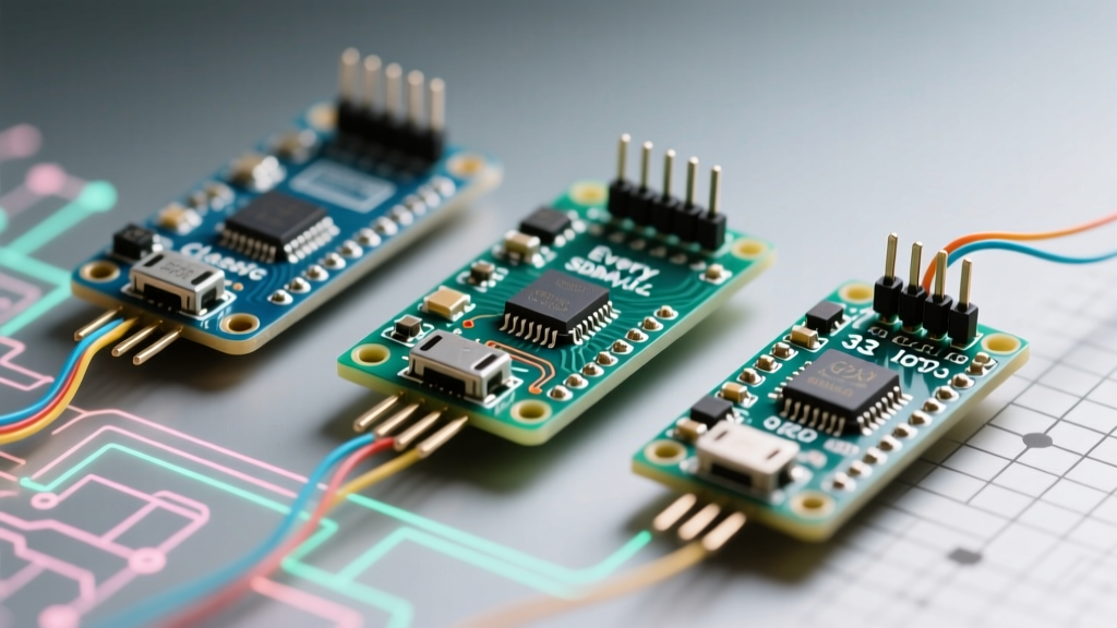

The Evolution of the Nano Form Factor
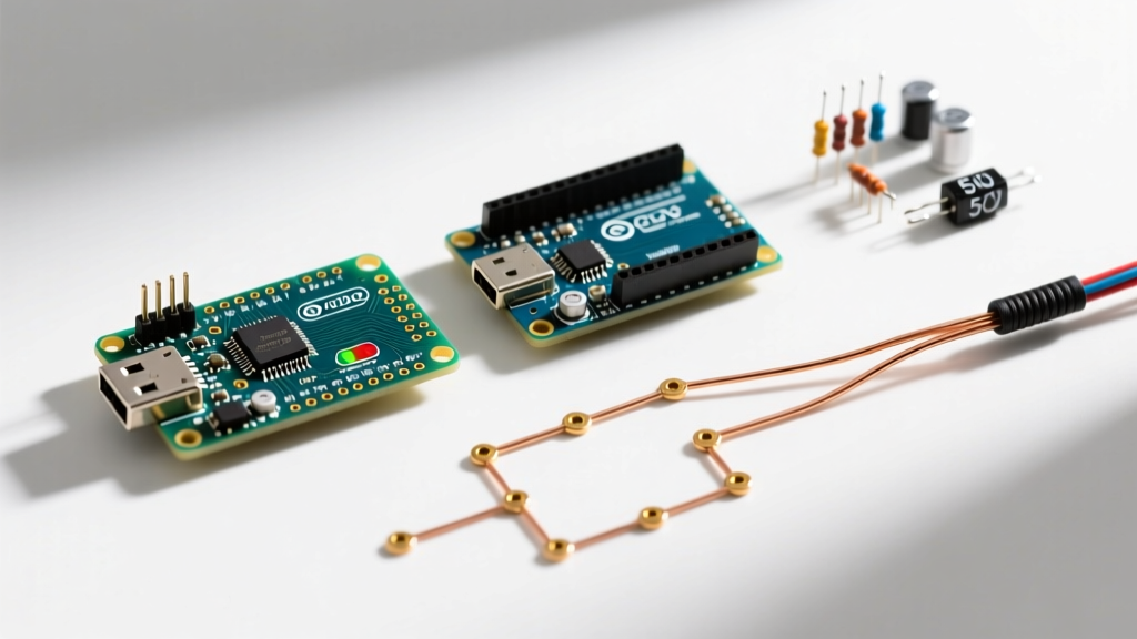
The original Arduino Nano revolutionized breadboard prototyping by shrinking the Uno's ATmega328P footprint into a 30-pin DIP-compatible module. However, as the maker ecosystem has matured, the 'Nano' moniker has expanded into a diverse family of microcontrollers. When makers search for an arduino nano pin diagram today, they are often met with confusion: the physical footprint remains largely identical, but the underlying silicon, logic levels, and alternate pin functions have fractured across the Classic, Every, and 33 IoT variants.
In this comprehensive board review, we dissect the specific pinout capabilities, voltage tolerances, and hidden hardware routing differences between these three powerhouse boards. Whether you are designing a custom PCB carrier or wiring a breadboard prototype, understanding these electrical nuances is critical to avoiding catastrophic silicon failure.
Classic ATmega328P: The Baseline Arduino Nano Pin Map
The Arduino Nano Classic (and its ubiquitous Asian clones) relies on the 8-bit AVR ATmega328P. Its 30-pin layout is the gold standard for legacy shields and breadboard wiring.
Voltage and Current Realities
The Classic operates at a strict 5V logic level. While the ATmega328P datasheet lists an absolute maximum DC current of 40mA per I/O pin, experienced electrical engineers know this is a cliff-edge specification. Pushing a single pin to 40mA causes significant voltage sag and internal heating. The practical, continuous safe limit is 20mA per pin, with a hard ceiling of 200mA for the entire VCC/GND package combined.
Expert Warning: Never drive inductive loads (like raw relay coils or small DC motors) directly from the Classic Nano's digital pins. The resulting back-EMF spike will instantly fry the ATmega328P's GPIO pad. Always use a logic-level MOSFET or an optocoupler with a flyback diode.
The USB-UART Power Bottleneck
A frequently overlooked edge case involves the 5V pin. On genuine Classic Nanos using the FT232RL USB-UART bridge, the 5V pin is fed through a diode from the USB 5V bus, meaning you can only safely draw about 500mA minus the board's overhead. On cheaper 2026 market clones utilizing the CH340G or CH340C chip, the voltage regulation is often handled by a linear AMS1117-5.0 LDO. If you backfeed power into the 5V pin while connected to USB, you risk back-currenting the LDO and destroying the USB bridge.
Nano Every: ATmega4809 Pin Multiplexing & Hidden Pads
The Arduino Nano Every upgraded the silicon to the Microchip ATmega4809, an advanced 8-bit AVR that introduces massive RAM upgrades (6KB) and hardware multiplexing. While it is marketed as a drop-in replacement, the arduino nano pin layout hides a few critical deviations.
The I2C Routing Secret
On the Classic Nano, I2C is hardware-locked to pins A4 (SDA) and A5 (SCL). The Nano Every maps these via software to maintain backward compatibility. However, the ATmega4809 actually features a dedicated, independent I2C hardware bus routed to two hidden solder pads on the bottom of the PCB. If you are designing a custom carrier board for high-speed I2C sensor fusion, soldering directly to these bottom pads bypasses the PORTMUX software overhead and provides a cleaner signal path.
PORTMUX and Alternate Functions
The 4809 introduces a PORTMUX register, allowing you to route hardware SPI, UART, and PWM signals to alternate physical pins. This is a massive advantage for PCB designers who need to untangle messy trace routing, but it requires modifying the Arduino core variant files to expose these alternate pin states in the IDE.
Nano 33 IoT: The 3.3V SAMD21 Pin Trap
The Arduino Nano 33 IoT swaps the 8-bit AVR architecture for a 32-bit ARM Cortex-M0+ (SAMD21G18A). This board introduces the most dangerous pin trap for hobbyists: the shift to 3.3V logic.
Logic Level Translation is Mandatory
Unlike the Classic and Every, the SAMD21's GPIO pads are not 5V tolerant. Feeding a 5V signal from a standard HC-SR04 ultrasonic sensor or a 5V I2C display directly into a Nano 33 IoT digital input will permanently destroy the silicon gate. You must use a bidirectional logic level shifter (like the BSS138 MOSFET circuit) or a voltage divider for any 5V peripheral. According to SparkFun's Logic Levels Guide, ignoring VCC mismatches is the number one cause of dead microcontrollers in mixed-voltage prototyping environments.
True Analog Output (DAC)
Where the Classic and Every only offer PWM (pseudo-analog) output, the Nano 33 IoT features a dedicated 10-bit Digital-to-Analog Converter (DAC) on pin A0. This allows the board to output a true, continuous analog voltage waveform, making it vastly superior for audio synthesis, precision op-amp biasing, and analog control loops.
Comprehensive Arduino Nano Pin Comparison Matrix
Use the following matrix to select the correct board for your specific electrical requirements.
| Feature | Classic (ATmega328P) | Every (ATmega4809) | 33 IoT (SAMD21G18A) |
|---|---|---|---|
| Logic Level | 5V | 5V | 3.3V (Not 5V Tolerant) |
| Digital I/O Pins | 14 | 14 | 14 |
| PWM Pins | 6 | 6 | 11 |
| Analog Inputs | 8 | 8 | 8 |
| True DAC Output | No | No | Yes (Pin A0) |
| Dedicated I2C Pads | No (Shared with A4/A5) | Yes (Bottom SMD pads) | No (Shared with A4/A5) |
| Max I/O Current | 40mA (20mA safe) | 25mA (15mA safe) | 7mA (per pin group limits) |
| Architecture | 8-bit AVR | 8-bit AVR (Advanced) | 32-bit ARM Cortex-M0+ |
Source: Official Arduino Hardware Documentation and Microchip ATmega4809 Datasheet.
Real-World Wiring Edge Cases & Failure Modes
Beyond the datasheets, field testing reveals specific failure modes tied to the physical pin layouts of these boards.
- The AREF Voltage Trap (Classic & Every): The Analog Reference (AREF) pin defaults to the internal 5V rail. If you connect an external 3.3V reference to the AREF pin without first calling
analogReference(EXTERNAL)in your setup loop, you will short the internal 5V VCC rail to your 3.3V source, potentially damaging your external voltage regulator. - Vin Pin Dropout (All Variants): The 'Vin' pin is tied to the input of the onboard linear regulator. To achieve a stable 5V/3.3V output, you must supply at least 6.5V to 7V to Vin. Supplying 5V to the Vin pin will result in a VCC brownout (typically around 3.8V), causing erratic behavior, random resets, and failed I2C handshakes.
- Reset Pin Capacitance (33 IoT): The SAMD21 reset pin is highly sensitive to parasitic capacitance. If you wire a long, unshielded cable to the reset button pad for an external enclosure switch, environmental EMI can trigger spontaneous resets. Always use a shielded twisted pair and a 100nF decoupling capacitor close to the pin.
2026 Pricing and Clone Market Realities
When budgeting for fleet deployments or commercial prototyping, the cost per pin varies wildly. As of 2026, a genuine Arduino Nano Classic retails for roughly $24.50, driven by European manufacturing costs. However, high-quality Asian clones featuring the CH340C USB-UART bridge and gold-plated pins can be sourced for $4.50 to $6.00. These clones are electrically identical for 95% of hobbyist use cases, though they often lack the precise 16MHz crystal tuning required for high-baud-rate serial communications.
The Nano Every sits at a sweet spot of ~$13.50 for the genuine board, offering superior memory and hardware routing without the premium of the IoT family. The Nano 33 IoT commands ~$22.00, a premium justified by the integrated ESP32-based Wi-Fi/Bluetooth NINA module and the 32-bit ARM core, though its low current-sourcing pins require external buffer ICs for driving heavy loads.
Frequently Asked Questions
Can I use a Nano Every as a direct drop-in replacement for the Classic?
Physically and electrically (5V logic), yes. However, if your code relies on direct port manipulation (e.g., PORTD |= (1 << 2)), it will fail on the Every. The ATmega4809 uses a completely different memory-mapped I/O structure (VPORTs) compared to the ATmega328P. You must use standard digitalWrite() functions or rewrite your bitwise operations for the 4809 architecture.
Which Nano variant has the most PWM-capable pins?
The Nano 33 IoT dominates with 11 PWM pins, thanks to the SAMD21's advanced Timer/Counter (TC) and Timer/Counter for Control (TCC) modules. The Classic and Every are limited to 6 hardware PWM pins.
How do I safely interface a 5V I2C display with the Nano 33 IoT?
You must use a dedicated I2C level shifter (like the PCA9306 or a BSS138 breakout board). Do not rely on internal pull-up resistors, as the 3.3V pull-ups on the 33 IoT will not reliably cross the 5V logic high threshold (VIH) required by most 5V LCD character displays.