
Why the Arduino Nano Remains the Breadboard King in 2026
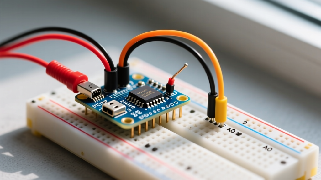
Despite the influx of modern RP2040 and ESP32-based development boards, the classic Arduino Nano (ATmega328P) remains the undisputed champion for prototyping on a standard solderless breadboard. Its DIP-30 footprint perfectly bridges the center divide of an 830-point breadboard, leaving exactly one row of exposed tie-points on either side for jumper wires. In 2026, while a genuine Arduino Nano retails for around $24.00, the market is flooded with high-quality third-party clones utilizing the CH340C USB-to-serial chip for roughly $4.50 to $6.00. For beginners building their first sensor circuit, the Nano offers a forgiving 5V logic environment, massive community support, and zero surface-mount soldering requirements.
The 5V vs 3.3V Logic Trap (Read Before Wiring)
The most common failure mode for beginners wiring a breadboard Arduino Nano to modern sensors is ignoring logic level voltages. The ATmega328P on the Nano operates at 5V logic. However, nearly all modern environmental, IMU, and display sensors (like the BME280, MPU6050, or SSD1306) operate strictly at 3.3V.
Expert Warning: Connecting a 5V I2C data line (SDA/SCL) directly to a 3.3V sensor will slowly degrade the sensor's internal GPIO protection diodes. While it might work for a few hours, it will eventually result in permanent I2C bus lockups or a fried sensor IC. Always use a bi-directional logic level converter for mixed-voltage breadboard circuits.
According to SparkFun's comprehensive guide on logic levels, exceeding the absolute maximum voltage rating of a CMOS chip by even 0.5V can cause latch-up conditions, leading to excessive current draw and thermal failure. We will integrate a logic level shifter into our first project to ensure long-term reliability.
Hardware Bill of Materials (BOM)
To build a robust, fail-safe environmental monitoring station, gather the following components. Prices reflect average 2026 market rates from major electronics distributors.
| Component | Specific Model / Part Number | Estimated Price | Purpose |
|---|---|---|---|
| Microcontroller | Arduino Nano (Clone with CH340C) | $5.00 | Main processing unit |
| Sensor | Adafruit BME280 Breakout (PID 2652) | $14.95 | Temp/Humidity/Pressure I2C sensor |
| Level Shifter | SparkFun Bi-Directional (BOB-12009) | $3.50 | Steps 5V I2C down to 3.3V safely |
| Prototyping | 830-Point Solderless Breadboard | $6.00 | Circuit assembly base |
| Wiring | 24 AWG Solid Core Hookup Wire Kit | $12.00 | Low-resistance breadboard connections |
Step-by-Step Breadboard Wiring Matrix
Proper power rail management is critical. We will use the Nano's onboard 3.3V voltage regulator to power the low-voltage (LV) side of our level shifter and the BME280 sensor. Note: The Nano's 3.3V pin can only supply roughly 150mA. The BME280 draws less than 1mA, making this perfectly safe.
Power and Ground Routing
- Nano 5V Pin → Breadboard Red Rail (Left)
- Nano GND Pin → Breadboard Blue Rail (Left)
- Nano 3V3 Pin → Breadboard Red Rail (Right)
- Bridge GND Rails: Connect Left Blue Rail to Right Blue Rail using a jumper wire.
Signal and I2C Routing (Via Logic Level Converter)
Place the SparkFun BOB-12009 level shifter across the center trench. Wire the high-voltage (HV) side to the Nano, and the low-voltage (LV) side to the BME280.
| Level Shifter Pin | Connects To | Wire Color Recommendation |
|---|---|---|
| HV | Nano 5V (Left Red Rail) | Red |
| GND (HV side) | Nano GND (Left Blue Rail) | Black |
| LV | Nano 3V3 (Right Red Rail) | Orange |
| GND (LV side) | Common GND (Right Blue Rail) | Black |
| HV1 | Nano A4 (SDA) | Yellow |
| HV2 | Nano A5 (SCL) | Green |
| LV1 | BME280 SDI (SDA) | Yellow |
| LV2 | BME280 SCK (SCL) | Green |
Finally, connect the BME280 VIN to the Right Red Rail (3.3V) and GND to the Right Blue Rail. Leave the BME280 CS and SDO pins unconnected for default I2C operation.
IDE Configuration & The 'Old Bootloader' Quirk
Before uploading code, you must configure the Arduino IDE (version 2.3+ recommended for 2026). If you purchased a clone Nano, it likely uses the CH340C USB-to-serial chip. Modern operating systems (Windows 11, macOS Sonoma/Sequoia, Ubuntu 24.04) include native CH340 drivers, eliminating the need for manual driver installation in most cases.
However, clone manufacturers frequently use older Optiboot bootloaders to save flash memory space. If you select the standard 'Arduino Nano' from the board manager and attempt to upload, you will encounter the dreaded avrdude: stk500_getsync() attempt 10 of 10: not in sync: resp=0x00 error.
The Fix: Navigate to Tools > Processor and select ATmega328P (Old Bootloader). This adjusts the upload baud rate from 115200 to 57600, matching the legacy bootloader's expectations. For deeper hardware specifications, refer to the official Arduino Nano hardware documentation.
First Project: BME280 Environmental Sensor Code
For this tutorial, we will read temperature, humidity, and barometric pressure. Install the Adafruit BME280 Library and the Adafruit Unified Sensor library via the Arduino Library Manager.
According to the Adafruit BME280 wiring and test guide, the default I2C address is 0x77. If your specific breakout board has the SDO pin tied high, the address shifts to 0x76. The code below initializes the sensor over the I2C bus and outputs formatted data to the serial monitor.
#include <Wire.h>
#include <Adafruit_Sensor.h>
#include <Adafruit_BME280.h>

#define SEALEVELPRESSURE_HPA (1013.25)

Adafruit_BME280 bme; // I2C

void setup() {
  Serial.begin(9600);
  while(!Serial); // Wait for serial monitor to open

  // Initialize BME280 on default I2C address 0x77
  if (!bme.begin(0x77)) {
    Serial.println("Could not find a valid BME280 sensor, check wiring!");
    while (1);
  }
  Serial.println("BME280 Initialized Successfully.");
}

void loop() {
  Serial.print("Temperature = ");
  Serial.print(bme.readTemperature());
  Serial.println(" *C");

  Serial.print("Pressure = ");
  Serial.print(bme.readPressure() / 100.0F);
  Serial.println(" hPa");

  Serial.print("Humidity = ");
  Serial.print(bme.readHumidity());
  Serial.println(" %");

  Serial.println("-------------------");
  delay(2000);
}
Advanced Troubleshooting & Edge Cases
Even with perfect wiring, breadboard prototypes can exhibit erratic behavior. Here is how to diagnose the three most common edge cases when building a breadboard Arduino Nano circuit.
1. I2C Bus Capacitance and Signal Degradation
Solderless breadboards introduce significant parasitic capacitance between adjacent metal clips. If your I2C wires exceed 15cm, the capacitance can round off the sharp edges of the SDA/SCL square waves, causing the BME280 to miss clock pulses. Solution: Keep I2C jumper wires under 10cm. If longer runs are required, add 4.7kΩ external pull-up resistors to the 3.3V LV side of the level shifter to strengthen the signal rise times.
2. The 'Charge-Only' USB Cable Trap
If your Nano's power LED illuminates when plugged into your PC, but the IDE shows no serial ports, you are likely using a charge-only USB Micro-B cable. These cables lack the internal D+ and D- data lines. Always verify your cable by testing it with a smartphone that supports data transfer, or keep a dedicated, verified data cable (like the AmazonBasics USB 2.0 A to Micro-B) in your toolkit.
3. Nano Reset Pin Floating Noise
The DTR (Data Terminal Ready) line from the USB chip automatically resets the Nano during code uploads. However, in high-EMI environments (near motors or relays), the reset pin can act as an antenna, picking up noise and causing spontaneous reboots. If your project resets randomly, place a 10μF electrolytic capacitor between the Nano's RESET and GND pins (anode to RESET, cathode to GND) to filter out high-frequency transients. Remember to remove this capacitor when uploading new code via USB, as it will block the auto-reset signal.
Next Steps for Your Prototyping Journey
Mastering the breadboard Arduino Nano setup lays the foundation for complex embedded systems. Once your BME280 is reliably logging data, consider integrating an RTC (Real Time Clock) module for timestamped logging, or upgrading to an ESP32 if your project eventually requires Wi-Fi telemetry. Always prioritize logic level safety, verify your USB data lines, and respect the physical limitations of solderless contacts.