
Why Arduino Mega 2560 Dimensions Dictate Your Project's Success
When designing complex robotics, industrial IoT control panels, or multi-axis CNC controllers in 2026, the microcontroller's physical footprint is just as critical as its processing power. The Arduino Mega 2560 remains the undisputed heavyweight for projects requiring massive I/O counts, offering 54 digital pins and 16 analog inputs. However, integrating this board into a final product requires a precise understanding of Arduino Mega 2560 dimensions, mounting hole geometries, and component overhangs. A miscalculation of even 1.5 millimeters can result in misaligned 3D-printed enclosures, shorted traces, or shattered PCBs during assembly.
This comprehensive mechanical review breaks down the exact physical specifications of the Mega 2560, compares it against modern alternatives like the Uno R4, and provides actionable hardware constraints for custom shield design and enclosure selection.
Exact Arduino Mega 2560 Dimensions & Tolerances
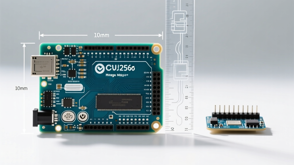
The official Arduino Mega 2560 Rev3 form factor is standardized, but manufacturing tolerances between genuine Italian-made boards and overseas clones can introduce slight variances. Below are the baseline mechanical specifications you need for your CAD models.
| Measurement Parameter | Metric (mm) | Imperial (inches) | Engineering Notes |
|---|---|---|---|
| PCB Length | 101.52 mm | 4.00" | Excludes USB/DC jack overhang |
| PCB Width | 53.30 mm | 2.10" | Widest point at header pins |
| Board Thickness (Genuine) | 1.60 mm | 0.063" | Standard FR4 fiberglass |
| Maximum Component Height | 14.20 mm | 0.56" | Top of the DC barrel jack |
| Weight | 37.0 g | 1.30 oz | Without headers or shields |
The Overhang Trap: USB-B and DC Barrel Jack
A frequent failure point in amateur enclosure design is ignoring the component overhang. The PCB length is exactly 101.52 mm, but the USB-B connector and the 2.1mm DC barrel jack protrude past the board edge. You must allocate an additional 2.0 mm to 2.5 mm of clearance at the front edge of your enclosure to accommodate these ports and the mating cables. If your 3D printed case is modeled exactly to 101.52 mm, the board will not seat flush against the rear standoffs.
Mounting Hole Geometry & Hardware Specifications
Securing the Mega 2560 requires precise alignment with its four mounting holes. Unlike smaller boards that use M2.5 hardware, the Mega 2560 utilizes larger clearance holes designed for M3 screws.
- Hole Diameter: 3.2 mm (Provides clearance for standard M3 pan-head or socket-head cap screws)
- Top Hole Spacing (Left to Right): 48.26 mm (1.90")
- Bottom Hole Spacing (Left to Right): 48.26 mm (1.90")
- Vertical Spacing (Top to Bottom): 96.52 mm (3.80")
Expert Warning: Never mount the Mega 2560 directly to a metal chassis without insulated standoffs. The bottom layer of the PCB contains critical ground planes and data traces routing to the ATmega2560 microcontroller. Using metal screws flush against a conductive surface will cause an immediate dead short. Always use nylon or anodized aluminum standoffs with a minimum height of 6mm to allow clearance for the protruding leads of through-hole components on the board's underside.
For sourcing high-quality hardware, mechanical engineers frequently rely on McMaster-Carr standoffs to ensure precise threading and non-conductive isolation when building industrial control boxes.
Clone vs. Genuine: The PCB Thickness Trap
While the official Arduino Mega 2560 documentation specifies a 1.6 mm FR4 PCB, the market is flooded with budget clones priced between $12 and $18 (compared to the $45-$50 genuine article). Many of these ultra-cheap clones cut costs by using 1.2 mm PCB substrates.
Why does this matter for dimensions? A 1.2 mm board lacks the rigidity to support the massive 18x2 female header pins used on the Mega. When you press a shield into these headers, the thinner PCB flexes. Over time, or in high-vibration environments like CNC routers, this flexing causes micro-fractures in the surface-mount MLCC capacitors and the solder joints of the ATmega16U2 USB controller. If you are designing a permanent installation, the $30 premium for a genuine board or a premium clone (like those from DFRobot or Seeed Studio) guarantees the 1.6 mm thickness required for long-term mechanical stability.
Arduino Mega 2560 Dimensions vs. Uno R4 vs. Uno R3
Upgrading or downgrading your platform requires understanding how the footprint shifts. The table below compares the Mega 2560 against the classic Uno R3 and the modern ARM-based Uno R4 Minima.
| Feature | Mega 2560 Rev3 | Uno R3 (Classic) | Uno R4 Minima |
|---|---|---|---|
| Length | 101.52 mm | 68.6 mm | 68.6 mm |
| Width | 53.3 mm | 53.4 mm | 53.4 mm |
| Mounting Holes | 4 (M3 Clearance) | 4 (M3 Clearance) | 4 (M3 Clearance) |
| Header Configuration | 3x 8-pin, 1x 10-pin, 2x 18-pin | 2x 8-pin, 2x 6-pin | 2x 8-pin, 2x 6-pin |
| Shield Compatibility | Requires Mega-specific shields | Standard Uno shields | Standard Uno shields |
Notice that while the width remains virtually identical across all three boards (around 53.3 mm), the length of the Mega is nearly 33 mm longer. This extra length is entirely dedicated to the additional digital and PWM headers. Enclosures designed for the Uno will physically reject the Mega by a massive margin.
Choosing the Right Enclosure in 2026
When moving from a breadboard prototype to a finished product, selecting the right enclosure is paramount. Based on current market offerings from top manufacturers like Hammond Manufacturing and Bud Industries, here is how you should approach housing the Mega 2560:
- Injection Molded ABS (e.g., Hammond 1593 Series): Ideal for desktop instruments. You will need to manually machine or laser-cut the side cutouts for the USB and DC jacks. Ensure the internal boss spacing matches the 48.26 mm x 96.52 mm mounting matrix.
- Aluminum Extrusion Cases: Excellent for EMI shielding in motor-control applications. You must design custom 3D-printed internal sleds that snap into the extrusion grooves, holding the Mega 2560 securely without relying on the PCB mounting holes.
- 3D Printed (PETG/ASA): For outdoor or UV-exposed projects, print your enclosure in ASA. Always design a 0.2 mm tolerance gap around the 53.3 mm width to account for FDM printer over-extrusion. A 53.5 mm internal cavity width ensures the board slides in without binding.
Custom Shield Design & Header Alignment Constraints
If you are designing a custom PCB shield that stacks on top of the Mega 2560, you must account for the notorious "wobbly header" issue. The Mega features two parallel 18-pin female headers. On genuine boards, these are machine-pinned and perfectly parallel. On budget clones, they are often hand-soldered with a slight angular deviation.
To prevent your custom shield from binding or cracking:
- Use long-leg machine pin headers (not stamped female headers) on your shield.
- Design your shield's PCB mounting holes to be 3.5 mm or 4.0 mm in diameter, rather than a tight 3.2 mm. This extra 0.8 mm of lateral play will absorb any angular misalignment from the host Mega board's headers.
- Keep all surface-mount components at least 2.0 mm away from the inner edge of the 18-pin headers to prevent physical collision with the Mega's USB-B port housing.
Final Mechanical Takeaways
Mastering the Arduino Mega 2560 dimensions is about looking beyond the basic 101.52 x 53.3 mm rectangle. It requires accounting for the 2.5 mm connector overhang, specifying M3 hardware with insulated standoffs, and verifying the 1.6 mm FR4 thickness to prevent board flex. By applying these precise mechanical constraints to your CAD models and enclosure designs, you ensure that your high-I/O projects are not only electrically sound but mechanically bulletproof for years of continuous operation.