
The Architecture of Buffer-Based OTA Updates
Over-The-Air (OTA) firmware updates are a non-negotiable feature for modern IoT deployments. While the standard Arduino Update.writeStream() method is sufficient for simple HTTP downloads, advanced architectures frequently require an Arduino ESP32 update from buffer. This approach utilizes Update.write(uint8_t *data, size_t len) to write discrete chunks of firmware data directly from RAM to the SPI flash. This is critical when receiving firmware via MQTT topics, Bluetooth Low Energy (BLE) DFU (Device Firmware Update), or custom UDP protocols where continuous TCP streams are unavailable or unreliable.
Writing from a buffer shifts the burden of memory management and timing directly onto the developer. In 2026, with the ESP32 Arduino Core v3.x (built on ESP-IDF v5.2), the underlying flash wear-leveling and partition management systems are highly optimized, but they still demand strict adherence to sector alignment and watchdog feeding. Choosing the right ESP32 variant—whether the classic WROOM-32, the powerhouse S3, or the budget-friendly C3—drastically alters how you must handle buffer allocation, chunk sizing, and flash write speeds.
Board Comparison Matrix: WROOM vs. S3 vs. C3
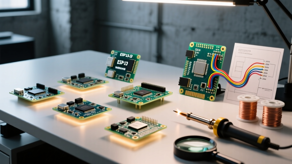
Not all ESP32 silicon is created equal. When performing buffer-based OTA updates, the available SRAM, flash interface speed, and cache architecture dictate your maximum safe buffer size and overall update latency. Below is a technical comparison of three dominant boards used in commercial and advanced DIY projects.
| Board Model | SRAM / PSRAM | Flash Interface | Optimal Buffer Size | Avg OTA Speed (1.5MB) | Typical 2026 Price |
|---|---|---|---|---|---|
| ESP32-WROOM-32E | 520KB / None | QSPI (80MHz) | 4096 bytes | ~4.2 seconds | $4.50 - $6.00 |
| ESP32-S3-WROOM-1 (N8R8) | 512KB / 8MB Octal | Octal SPI (80MHz) | 8192 - 16384 bytes | ~2.6 seconds | $7.50 - $10.00 |
| ESP32-C3-MINI-1 | 400KB / None | QSPI (80MHz) | 4096 bytes | ~5.5 seconds | $2.50 - $3.50 |
Deep Dive: The ESP32-S3 PSRAM Advantage
The ESP32-S3 introduces a massive advantage for buffer-based OTA: Octal PSRAM. On the classic WROOM-32, finding a contiguous 512KB block of SRAM at runtime is nearly impossible due to heap fragmentation. The S3, however, allows you to allocate a massive multi-megabyte buffer in PSRAM. Advanced developers use this to download the entire firmware image into PSRAM first, verify the SHA-256 hash, and only then initiate the flash write sequence. This completely isolates network jitter from flash operations, virtually eliminating OTA bricking caused by mid-write network timeouts.
Critical Partition Scheme Considerations
Before writing a single byte to the flash, your partition table must support the incoming firmware size. The default Arduino partition scheme (default.csv) allocates only 1.2MB for the app0 and app1 partitions. If your compiled binary is 1.3MB, Update.begin(size) will instantly fail and return false.
- min_spiffs.csv: Allocates ~1.9MB per OTA partition. Ideal for feature-rich firmware with heavy libraries (e.g., TensorFlow Lite Micro, LVGL).
- huge_app.csv: Allocates ~3MB for a single app partition. Disables OTA entirely. Avoid this for production IoT devices.
- Custom CSV: For ESP32-S3 boards with 16MB flash, developers frequently create custom partition tables featuring three OTA slots (app0, app1, app2) to implement a 'golden fallback' partition that is never overwritten via OTA.
According to the Espressif OTA Documentation, the update library requires the incoming binary size to be strictly less than or equal to the target partition size, minus the overhead for the image header and signature verification blocks.
Step-by-Step: Safe Buffer Writing Implementation
Implementing the Update.write() function requires a precise sequence to avoid corrupting the flash memory. Below is the architectural flow for a robust buffer-based OTA routine.
- Initialize the Update: Call
Update.begin(firmware_size_in_bytes). This erases the target OTA partition. Warning: Erasing 1.5MB takes roughly 1.2 seconds and blocks the CPU. - Align the Buffer: Ensure your incoming data buffer is aligned to 4-byte boundaries. While the ESP-IDF handles unaligned writes internally, aligned buffers prevent unnecessary read-modify-write cycles in the flash controller.
- Write in Chunks: Pass your buffer to
Update.write(buffer, chunk_length). The optimal chunk size is 4096 bytes, matching the standard SPI flash sector size. - Feed the Watchdog: The Task Watchdog Timer (TWDT) in Arduino Core v3.x defaults to a strict 5-second timeout. You must call
yield()orvTaskDelay(1)inside your write loop. - Finalize and Verify: Call
Update.end(true). This finalizes the flash write, sets the boot partition to the newly written slot, and optionally triggers a reboot.
Expert Tip: Never usedelay()inside an OTA write loop.delay()yields to the FreeRTOS scheduler but can interfere with the TCP/IP stack's background processing if you are simultaneously receiving data. UsevTaskDelay(1)to yield precisely one tick, keeping the network stack responsive while satisfying the TWDT.
Real-World Failure Modes and Edge Cases
Even with perfect code, hardware realities introduce edge cases that can brick a device in the field. Understanding these failure modes is what separates hobbyist code from production-grade firmware.
1. Power Supply Brownouts During Flash Erase
Erasing a flash sector draws a significant current spike (up to 300mA for some Winbond W25Q series chips). If your ESP32 is powered by a marginal 3.3V LDO (like the cheap AMS1117 found on $3 clone boards), the voltage will dip below the 2.7V brownout threshold. The ESP32's internal BOD (Brownout Detector) will instantly reset the chip mid-erase, leaving the OTA partition in an uninitialized state. Solution: Disable the BOD during OTA via esp_brownout_disable(), or use a high-quality buck converter (e.g., TI TPS62740) capable of handling transient spikes.
2. SPI Flash Cache Misses
When writing to the flash, the ESP32 must temporarily disable the SPI flash cache to execute write/erase commands. If your firmware is actively executing code from the flash (which it always is, unless running entirely from IRAM), the CPU will stall. If your buffer write loop is interrupted by a high-priority hardware interrupt that attempts to read a variable stored in flash, the system will trigger a Cache disabled but cached memory region accessed panic. To prevent this, ensure your OTA task runs at a lower priority and avoid placing interrupt service routines (ISRs) in flash memory; use the IRAM_ATTR macro for all ISRs.
3. MQTT Payload Fragmentation
When using MQTT for OTA, the standard maximum payload size is often limited to 256 bytes or 1KB by the broker. Reassembling these fragments into a 4096-byte buffer before calling Update.write() is mandatory. Writing 256-byte chunks directly to the flash will cause massive write amplification, degrading the flash lifespan and increasing OTA time by up to 400%. Always buffer the network fragments in RAM until you hit the 4096-byte sector boundary.
Expert Verdict: Which Board Wins for High-Frequency OTA?
For deployments requiring frequent, large-scale OTA updates (e.g., edge AI models updating weekly), the ESP32-S3-WROOM-1 is the undisputed champion. Its Octal SPI flash interface cuts write times in half compared to the classic WROOM, and the availability of PSRAM allows for complete firmware staging and cryptographic verification before the flash is ever touched. For cost-sensitive, static sensor nodes where OTA is a rare emergency fallback, the ESP32-C3 provides ample performance at a fraction of the BOM cost, provided you strictly manage your 400KB SRAM envelope.
Mastering the Arduino ESP32 update from buffer requires moving beyond simple copy-paste tutorials. By respecting flash sector alignments, managing the TWDT, and selecting the appropriate silicon for your memory architecture, you can build OTA systems that survive the harsh realities of field deployment. For deeper insights into the underlying ESP-IDF partition APIs, refer to the Arduino ESP32 Core GitHub Repository and the official Espressif hardware design guidelines.