
The Evolution of the Arduino Nano Power Input Ecosystem
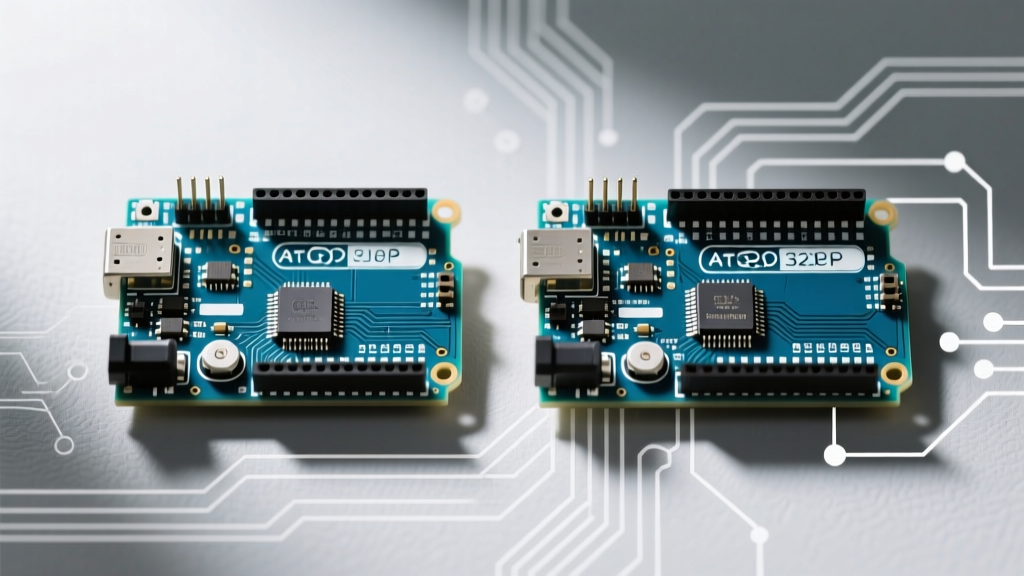
When engineers, hobbyists, and IoT developers discuss the Arduino Nano power input specifications, they are often referencing the classic ATmega328P-based board from 2008. However, as of 2026, the 'Nano' is no longer a single microcontroller; it is a sprawling hardware ecosystem. The 45x18mm footprint remains the industry standard for compact embedded deployments, but the underlying power trees have radically diverged. Understanding how to properly route voltage into these boards is critical, as applying classic Nano power logic to a modern Nano 33 IoT or RP2040 Connect can lead to immediate component failure or severe thermal throttling.
This ecosystem overview dissects the power input architectures across the Nano family, detailing voltage regulator topologies, thermal limitations, and real-world failure modes. Whether you are designing a 12V industrial sensor node or a 3.7V LiPo-powered wearable, mastering the specific power delivery network (PDN) of your chosen Nano variant is the first step toward a reliable deployment.
Ecosystem Comparison Matrix: Power Trees Across Variants
Before wiring your project, you must identify which Nano variant you are using. The logic levels and VIN (Voltage Input) tolerances vary drastically across the ecosystem.
| Board Variant | Core MCU | Logic Level | VIN Pin Range | Regulator Topology | Max Recommended Current |
|---|---|---|---|---|---|
| Nano Classic (Rev 3) | ATmega328P | 5.0V | 7V - 12V | Linear LDO (NCP1117) | ~400mA (Thermal Limited) |
| Nano Every | ATmega4809 | 5.0V | 7V - 18V | Linear LDO | ~500mA |
| Nano 33 IoT | SAMD21G18A | 3.3V | 4.5V - 21V | Switching Step-Down | ~1000mA |
| Nano 33 BLE | nRF52840 | 3.3V | 4.5V - 21V | Switching Step-Down | ~1000mA |
| Nano RP2040 Connect | RP2040 | 3.3V | 4.5V - 21V (via PMIC) | PMIC (NXP PCA9420) | ~2000mA (Combined) |
Deep Dive: The Classic Nano and the Linear LDO Trap
The original Arduino Nano relies on the NCP1117ST50T3G, a 5V linear low-dropout regulator (LDO) manufactured by ON Semiconductor. According to the ON Semi NCP1117 datasheet, this SOT-223 packaged regulator can theoretically output up to 1A of current. However, theoretical limits ignore the thermal reality of the Nano's compact PCB.
The Thermal Math of Linear Regulation
Linear regulators operate by burning excess voltage as heat. The power dissipated (Pd) is calculated as: Pd = (Vin - Vout) × I.
- Scenario: You power a Classic Nano via the VIN pin with a 12V wall adapter. Your circuit draws 150mA (sensors, relays, and the MCU).
- Calculation: (12V - 5V) × 0.15A = 1.05 Watts of heat.
- Thermal Resistance: The SOT-223 package without a dedicated copper pour heatsink has a junction-to-ambient thermal resistance of roughly 100°C/W.
- Result: The regulator's internal junction temperature will rise by 105°C above ambient. In a 25°C room, the junction hits 130°C, triggering the internal thermal shutdown protection. Your Nano will randomly reboot under load.
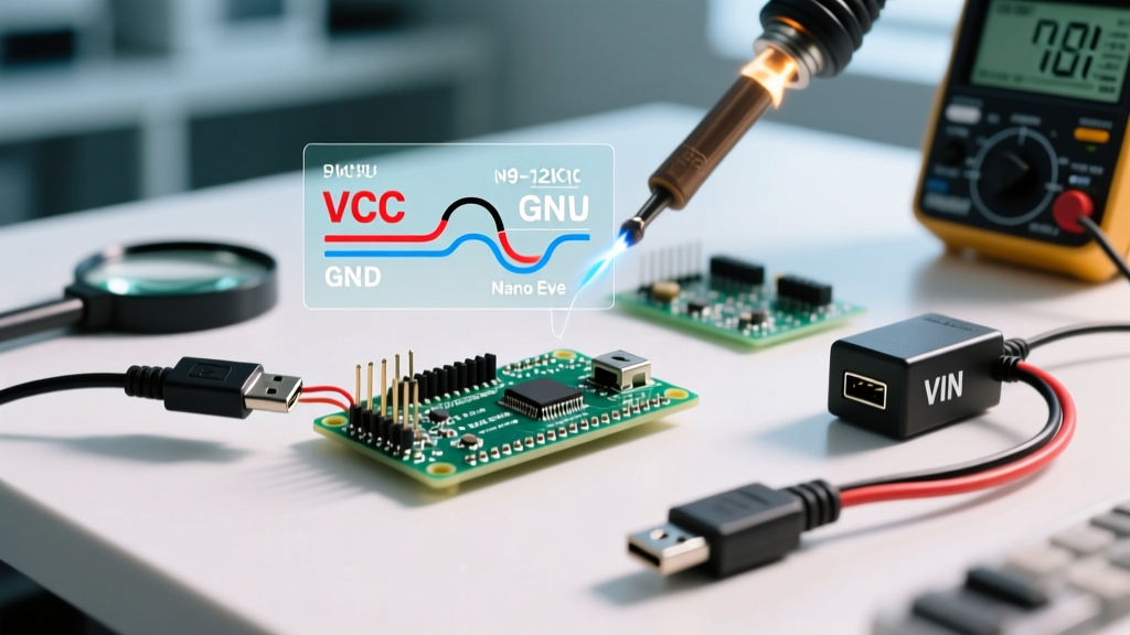
Expert Insight: If your 5V Classic Nano project requires more than 100mA of continuous current and your source voltage is above 7V, you must bypass the onboard LDO. Use an external buck converter (like a Pololu D24V50F5) to step down the voltage to 5V, and inject it directly into the 5V pin. This bypasses the LDO entirely, achieving 90%+ efficiency compared to the LDO's ~41% efficiency.
The 3.3V Shift: Nano 33 IoT and BLE Power Architectures
As the ecosystem expanded to include Wi-Fi (NINA-W102) and Bluetooth (nRF52840), the power requirements shifted. The official Arduino Nano 33 IoT documentation confirms a 3.3V logic level. To support a wider array of industrial power supplies and battery packs, Arduino replaced the inefficient linear LDO with a high-voltage switching step-down regulator capable of accepting up to 21V on the VIN pin.
Advantages of the Switching Topology
Unlike the Classic Nano, feeding 12V into the VIN pin of a Nano 33 IoT does not result in massive thermal waste. The switching regulator efficiently chops the 12V down to 3.3V with minimal heat generation. This makes the IoT and BLE variants vastly superior for automotive (12V-14V) or solar (18V panel) deployments where thermal management is constrained by small enclosures.
The 5V Pin Warning on 3.3V Boards
A critical edge case in the ecosystem is the presence of a 5V pin on the Nano 33 IoT and BLE boards. This pin is an output from the USB 5V line, regulated down from the USB bus. It is not a 5V input pin. Injecting 5V into this pin while the board is running on 3.3V logic can backfeed the USB controller and destroy the SAMD21 or nRF52840 MCU. Always treat the 5V pin on 3.3V Nano variants as an output-only rail limited to ~500mA (dictated by the USB host or hub).
The PMIC Revolution: Nano RP2040 Connect
The most advanced power tree in the ecosystem belongs to the Nano RP2040 Connect. Instead of a simple LDO or discrete switching regulator, it utilizes the NXP PCA9420 Power Management IC (PMIC). This chip is a game-changer for battery-powered IoT deployments.
Integrated Battery Management
The PCA9420 integrates a Li-Ion/Li-Po linear charger, two buck converters, and two LDOs. According to the Arduino RP2040 Connect hardware guide, this allows developers to connect a 3.7V LiPo battery directly to the dedicated battery pads on the underside of the board. The PMIC handles the charge profile (CC/CV), path management (switching between USB power and battery seamlessly), and voltage regulation for the RP2040 and the onboard ESP32-C3 Wi-Fi module.
Quiescent Current and Deep Sleep
When designing off-grid nodes, quiescent current (Iq) is the enemy. The Classic Nano draws roughly 15mA to 20mA just to keep the USB-to-Serial CH340/FTDI chip and power LED alive, making deep sleep nearly useless without hardware modification (cutting the LED jumper and desoldering the USB IC). The RP2040 Connect, leveraging the PMIC and the RP2040's native dormant states, can achieve vastly superior sleep currents, provided the peripheral I2C/SPI sensors are also powered down via a controlled MOSFET gate.
Real-World Failure Modes and Troubleshooting
Even with the correct board selected, improper power routing leads to field failures. Here are the most common edge cases encountered in the Nano ecosystem:
- USB Backfeed Ground Loops: If you power the Nano via the VIN pin (e.g., from a 12V industrial supply) and simultaneously connect the USB cable for debugging, differences in ground potential between the 12V supply and the PC's USB ground can cause current to flow backward through the USB shield. This can fry the PC's USB port or the Nano's USB protection diode. Solution: Use an isolated USB hub or a digital isolator for serial debugging in high-voltage environments.
- Capacitive Inrush Tripping PTC Fuses: The Nano features a resettable PTC polyfuse on the USB VBUS line. If you connect large decoupling capacitors (e.g., >1000µF) directly to the 5V pin, the inrush current upon USB plug-in can exceed the 500mA trip threshold, causing the fuse to open and the board to appear dead for several minutes until the fuse cools.
- Brownout Detection (BOD) False Triggers: On the Classic Nano, if the VIN voltage sags below the LDO dropout voltage (roughly 6.2V), the 5V rail drops. If it falls below the ATmega328P's Brownout Detection threshold (usually set to 4.3V or 2.7V via fuses), the MCU will reset. In motor-control applications, voltage dips from inductive kickback frequently cause this. Solution: Add a Schottky diode and a large hold-up capacitor (e.g., 470µF) on the VIN line to ride out transient dips.
Strategic Power Selection Framework
To finalize your hardware design, use this decision matrix for your Arduino Nano power input strategy:
- For 5V Logic / Bench Prototyping: Use the Classic Nano powered via USB. Cost-effective and universally compatible with 5V sensors.
- For 12V-24V Industrial Sensors: Use the Nano 33 IoT or RP2040 Connect via the VIN pin. The switching regulators handle high input voltages without thermal throttling.
- For Wearables and Mobile IoT: Use the Nano RP2040 Connect with a 3.7V LiPo cell soldered to the bottom pads. Refer to Adafruit's LiPo battery guide for safe charging and discharge curve management.
- For Ultra-Low Power Remote Nodes: Avoid the onboard regulators entirely. Use a bare-bones ATmega328P or RP2040 on a custom PCB, or inject regulated 3.3V directly into the 3.3V pin of a Nano 33 IoT, bypassing all onboard power conversion losses.
Mastering the Arduino Nano power input ecosystem requires looking past the silkscreen labels and understanding the silicon beneath. By matching the regulator topology to your specific voltage source and current draw, you ensure long-term stability, thermal safety, and optimal power efficiency for your embedded projects.