
The Hidden Dangers in 'Harmless' Components
When assembling or troubleshooting a printed circuit board (PCB), engineers often focus their safety protocols on active semiconductors, high-voltage power supplies, and mains wiring. However, passive electronic components—resistors, capacitors, inductors, and transformers—present unique, frequently underestimated hazards. While they do not amplify signals, they store energy, generate intense localized heat, and can fail catastrophically if pushed beyond their physical or environmental limits.
As component miniaturization accelerates in 2026, with 01005 (0.4mm x 0.2mm) surface-mount packages becoming standard in high-density interconnect (HDI) boards, the margin for mechanical and thermal error has vanished. This guide details the critical safety and best-practice frameworks required to handle, test, and deploy passive electronic components without risking personal injury or board-level destruction.
⚠ Lethal Energy Warning: A standard 400V, 470µF aluminum electrolytic capacitor stores approximately 37.6 Joules of energy. According to OSHA's electrical safety guidelines, as little as 5 Joules can induce ventricular fibrillation. Never assume a powered-down board is safe to touch without verifying passive discharge states.
Capacitor Safety: Discharge Protocols and Dielectric Breakdown
Capacitors are the most dangerous passive electronic components in a de-energized circuit. Beyond the immediate shock hazard of a charged dielectric, capacitors suffer from dielectric absorption—a phenomenon where the dielectric material slowly releases trapped charge back to the plates hours or even days after being shorted.
Step-by-Step High-Voltage Discharge Procedure
Never short a high-voltage capacitor directly with a screwdriver. The instantaneous current spike ($I = C rac{dv}{dt}$) can vaporize metal, destroy the capacitor's internal bond wires, and weld your tool to the terminals.
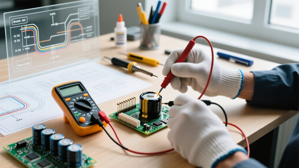
- Verify Voltage: Use a high-impedance digital multimeter (DMM) rated for CAT III/IV, such as the Fluke 87V, to check the terminal voltage.
- Select the Bleeder Resistor: Use a wirewound power resistor. A 10kΩ, 10W resistor (e.g., Ohmite 20J10KE) safely dissipates the energy over several seconds without exceeding its pulse-withstand rating.
- Apply the Probe: Mount the resistor on an insulated, fiberglass-handled probe. Hold the resistor leads across the capacitor terminals for a minimum of five time constants ($5 au = 5 imes R imes C$).
- Re-verify: Check the voltage again with the DMM. Due to dielectric absorption, wait 10 minutes and measure a third time before handling the component bare-handed.
Capacitor Failure Modes and Mitigation Matrix
| Component Type | Primary Failure Mode | Safety Hazard | Best Practice Mitigation |
|---|---|---|---|
| Aluminum Electrolytic | Electrolyte boiling / venting | Shrapnel, chemical burns, fire | Ensure correct polarity; use over-pressure vent types (e.g., Nichicon UHE series); maintain 105°C rated parts for 85°C environments. |
| Tantalum (Solid) | Thermal runaway short-circuit | Violent ignition, toxic smoke | Derate voltage by 50%; never use in high-surge input filter stages without current limiting. |
| Ceramic (MLCC) | Micro-cracking / piezoelectric ringing | Latent short circuits, board fire | Keep >2mm away from board bend zones; use flexible termination (Soft-Termination) MLCCs in high-stress areas. |
Resistor Thermal Runaway and Power Derating
Resistors are often treated as simple current-limiting devices, but their thermal management is a critical safety discipline. A resistor's published wattage (e.g., 1/4W or 0.25W) is only valid at a specific ambient temperature, typically 70°C. Above this 'knee' temperature, the component must be linearly derated to zero watts at its maximum operating temperature (usually 155°C for standard carbon/metal film).
Calculating Real-World Thermal Limits
If you are designing a power supply operating in an enclosed chassis where the ambient temperature reaches 90°C, a standard Yageo CFR-25 (1/4W) resistor is already derated by roughly 23%. It can only safely dissipate 0.19W. Pushing 0.25W through it will cause the epoxy coating to char, potentially igniting nearby components or causing the resistive element to open-circuit unpredictably.
- Flameproof Requirements: In mains-connected circuits, always specify flameproof metal oxide resistors (e.g., Vishay PR02 series). These are coated with non-combustible silicone and are designed to open safely without catching fire during catastrophic overload.
- Pulse Withstand vs. Continuous Power: For snubber circuits or inrush limiting, continuous wattage is irrelevant. You must consult the manufacturer's single-pulse energy chart. A 2W carbon composition resistor can survive a 500W pulse for 10 milliseconds, whereas a 2W thick-film resistor will instantly vaporize its trace element under the same conditions.
- Standard Rectifiers (e.g., 1N4007): Adequate for slow-switching relays (under 1 kHz). However, their slow reverse recovery time ($t_{rr}$) makes them useless for high-frequency PWM motor drivers.
- Schottky Diodes (e.g., 1N5819 or SS34): Mandatory for switching frequencies above 10 kHz. Their near-zero reverse recovery time clamps the voltage spike before the driving MOSFET can enter avalanche breakdown.
- RC Snubber Networks: When a flyback diode is too slow or causes relay contact bouncing, an RC snubber (e.g., 100Ω in series with a 100nF X2-rated film capacitor) placed across the inductor safely dissipates the high-frequency ringing as heat in the resistor.
- Bake Before Rework: If an MSL 3 or higher component reel has been exposed to >10% RH for over 168 hours, it must be baked at 125°C for 24 hours before soldering.
- Board Edge Clearance: Never place large MLCCs (e.g., 1206 or 1210 case sizes) within 3mm of a PCB router cutout or V-score line. The mechanical stress of depaneling the board will instantly induce flex-cracks in the ceramic dielectric.
- ESD Grounding: When hand-soldering precision wirewound resistors or RF chip inductors, use a grounded ESD wrist strap and a dissipative mat. Static spikes exceeding 2kV can subtly alter the inductance value of micro-coils by magnetizing their ferrite cores.
- LCR Meter: The Keysight E4980AL remains the industry benchmark for measuring capacitance, inductance, and equivalent series resistance (ESR) at various frequencies, allowing you to detect degraded electrolytic capacitors before they fail in-circuit.
- Thermal Imaging: A FLIR C5 thermal camera is indispensable for spotting thermal runaway. A resistor operating safely at 70°C will emit a dull orange glow on a thermal overlay; one operating at 130°C due to improper derating will show up as a glaring white hotspot, warning you of an impending fire hazard before the solder even melts.
Inductor and Transformer Kickback Mitigation
Inductors resist changes in current. When the current flow through an inductor is suddenly interrupted (such as a MOSFET switching off), the collapsing magnetic field induces a massive reverse voltage spike ($V = -L rac{di}{dt}$). This inductive kickback can easily exceed the breakdown voltage of your switching transistor, resulting in an explosive semiconductor failure that sends shrapnel across the workbench.
Flyback Diode Selection and Snubber Networks
To safely manage passive electronic components like inductors, you must provide a path for the stored energy to dissipate. The All About Circuits textbook on inductive kickback provides an excellent foundational overview of why this occurs, but real-world 2026 implementations require precise component selection.
ESD and Moisture Sensitivity Levels (MSL) for Passives
While electrostatic discharge (ESD) is traditionally associated with destroying sensitive CMOS logic gates, modern passive electronic components are highly susceptible to both ESD and moisture ingress. The ESD Association standards outline strict handling protocols that apply equally to high-value RF inductors and precision thin-film resistors.
Mechanical and Moisture Best Practices
Multilayer Ceramic Capacitors (MLCCs) are essentially brittle sandwiches of barium titanate and metal electrodes. If an MLCC absorbs moisture from the air (classified under IPC/JEDEC J-STD-020 Moisture Sensitivity Levels), the rapid heat of a 260°C reflow oven turns that moisture into steam. The resulting internal pressure causes 'popcorning'—a violent delamination that cracks the ceramic and creates intermittent short circuits.
MLCC Placement and Handling Rules
Essential Testing Gear for 2026 Workbenches
To safely verify the integrity of passive electronic components, your test equipment must offer high resolution and robust protection ratings. Relying on cheap, uncalibrated meters introduces severe safety risks when measuring components in high-energy circuits.
Frequently Asked Questions
Can a resistor fail as a short circuit?
It is exceedingly rare. Carbon film and metal oxide resistors almost universally fail 'open' due to the resistive element burning out. However, high-voltage chip resistors can fail short if surface arcing carbonizes the epoxy coating, creating a conductive path. Always use series-stacked resistors in high-voltage dividers to prevent single-point short failures.
Why do my ceramic capacitors 'sing' or whine?
This is the piezoelectric effect. Class 2 dielectrics (like X7R and Y5V) physically deform when subjected to AC voltage, causing the PCB to act as a sounding board. While mostly an acoustic annoyance, severe vibration can fatigue solder joints over time. Use Class 1 (C0G/NP0) dielectrics in audio paths to eliminate this microphonic effect entirely.