
Building Your Visual Component Library for DIY Electronics
Every successful electronics hobbyist reaches a point where memorizing part numbers isn't enough; you need instant visual recognition. Whether you are prototyping an Arduino-based weather station or building a standalone 555-timer astable multivibrator, having a reliable electronic components list with images and visual identification markers is critical. In 2026, the market is flooded with both high-quality name-brand parts and budget generic kits. Knowing exactly what a 1% metal-film resistor looks like compared to a 5% carbon-film one, or identifying the cathode on a surface-mount LED, will save you hours of debugging.
This guide serves as your visual and technical reference for the most common through-hole and surface-mount components found in modern DIY breadboard kits, complete with physical identification traits, real-world tolerances, and 2026 market pricing.
Passive Components: The Backbone of Every Circuit
1. Resistors: Decoding the Color Bands

Resistors limit current flow and divide voltages. Visually, they are cylindrical with axial wire leads. According to SparkFun's Resistor Tutorial, the body color immediately tells you the tolerance and material:
- Carbon Film (Brown Body): Typically 5% tolerance (gold band). Used in non-critical applications like basic LED current limiting. Cost: ~$0.01 per unit in bulk.
- Metal Film (Blue Body): Typically 1% tolerance (brown band). Essential for precision voltage dividers and analog sensor conditioning. Cost: ~$0.02 per unit.
Pro-Tip for Breadboarding: Always use 1/4W (0.25W) resistors for standard 5V and 3.3V logic circuits. If a resistor feels hot to the touch (exceeding 60°C), you are likely exceeding its power dissipation rating. Calculate using P = I²R.
2. Capacitors: Ceramic Discs vs. Electrolytic Cylinders

Capacitors store and release electrical energy. The Adafruit Capacitor Guide highlights two primary visual categories you will encounter in any starter kit:
- Ceramic Disc Capacitors: Small, non-polarized, usually orange or yellow. They use a three-digit EIA code. For example, a marking of
104means 10 × 10⁴ picofarads (100,000 pF or 100 nF or 0.1 µF). These are your go-to bypass/decoupling capacitors for IC power pins. - Electrolytic Capacitors: Cylindrical, polarized, and wrapped in a plastic sleeve. Critical Visual Marker: A prominent grey or white stripe with minus signs (−) running down one side indicates the negative (cathode) lead. The positive lead is physically longer on new parts. Reversing polarity on a 16V or 25V electrolytic capacitor will cause it to vent or explode.
Optoelectronics: LEDs and Photodiodes
3. Standard 5mm Through-Hole LEDs

Light Emitting Diodes (LEDs) are polarized. When examining a standard 5mm T-1 3/4 LED, look for three visual cues to identify the negative cathode:
- Lead Length: The shorter leg is the cathode (negative).
- Flange Flat Spot: The plastic base rim has a flat edge on the cathode side.
- Internal Structure: Looking through the clear epoxy lens, the larger internal metal piece (the anvil) is the cathode; the smaller post is the anode.
Electrical Specifics: Never wire an LED directly to a voltage source without a resistor. In 2026, high-efficiency LEDs dominate the market. A standard red LED has a forward voltage (Vf) of ~2.0V, while modern blue and pure white LEDs require ~3.2V. For a 5V Arduino output targeting 20mA, use a 150Ω resistor for red, and a 100Ω resistor for blue/white.
Active Components and Integrated Circuits (ICs)
4. Transistors (TO-92 Package)
The TO-92 package is the most common form factor for small-signal transistors like the ubiquitous 2N2222 (NPN) or 2N3906 (PNP). When viewing the transistor with the flat face toward you and the leads pointing down, the standard pinout from left to right is Emitter (E), Base (B), and Collector (C). Warning: Always verify the pinout via the specific manufacturer's datasheet, as Japanese (JIS) and European (Pro Electron) numbering conventions sometimes swap the C and E pins.
5. Integrated Circuits (DIP Packages)

Dual In-line Package (DIP) ICs, such as the legendary Texas Instruments NE555 Timer or the CD4017BE decade counter, plug perfectly into standard solderless breadboards. Visual orientation is non-negotiable:
- The Notch: A semi-circle cutout at one end of the IC body indicates the 'top'.
- The Dot: A small indented dot in the top-left corner (relative to the notch) designates Pin 1.
- Reading Pins: Pins are numbered counter-clockwise. Pin 1 is top-left, the highest pin number is top-right, and the sequence continues down the right side and back up the left.
Edge Case Warning: Plugging a DIP IC in backwards on a breadboard will instantly reverse the VCC and GND pins. In CMOS logic (like the 4000 series), this will permanently destroy the silicon die in milliseconds due to forward-biasing internal protection diodes.
Visual ID & Breadboard Placement Matrix
Use this quick-reference table when sorting your kit or troubleshooting a breadboard layout.
| Component Type | Visual Polarity Marker | Breadboard Placement Rule | Common Failure Mode |
|---|---|---|---|
| Resistor | None (Non-polarized) | Any orientation; span across the center trench. | Overheating (discoloration) due to exceeding 1/4W limit. |
| Ceramic Capacitor | None (Non-polarized) | Place adjacent to IC VCC/GND pins for decoupling. | Mechanical fracture of leads from excessive bending. |
| Electrolytic Capacitor | Grey stripe with minus (−) signs | Negative lead to GND rail; positive to VCC. | Venting/explosion if reverse-biased or over-volted. |
| Diode (1N4007) | Silver/White band on one end | Silver band points toward the negative (cathode) side. | Thermal runaway if current exceeds 1A continuous. |
| DIP Integrated Circuit | Notch and Pin 1 dot | Must straddle the center trench; notch faces 'up'. | Bent pins hidden under the IC body during insertion. |
SMD vs. Through-Hole: A Visual Shift in 2026
While through-hole components remain the standard for breadboard prototyping, modern DIY kits increasingly include Surface Mount Devices (SMD) for custom PCB soldering. Visual identification changes drastically here:
- SMD Resistors: Tiny black rectangles with printed numbers. A marking of
472means 47 × 10² (4.7 kΩ). Size codes like '0805' refer to physical dimensions (0.08 x 0.05 inches), requiring fine-tipped tweezers and a magnifying lamp. - SMD LEDs: Often feature a green 'T' mark or a small triangle printed on the underside to denote the cathode. Unlike through-hole LEDs, you cannot rely on leg length.
Sourcing Economics: Building Your 2026 Kit
If you are assembling your first comprehensive kit, avoid buying individual components from retail storefronts, where a single 555 timer might cost $2.50. Instead, leverage bulk marketplace economics. In 2026, a high-quality 600-piece DIY starter kit (including a solderless breadboard, jumper wires, and the core passives/actives listed above) ranges from $28.00 to $42.00 on platforms like Amazon or AliExpress. For guaranteed authenticity and tighter 1% tolerances on resistors, order directly from authorized distributors like Mouser or DigiKey, though shipping minimums usually apply.
Troubleshooting with a Multimeter
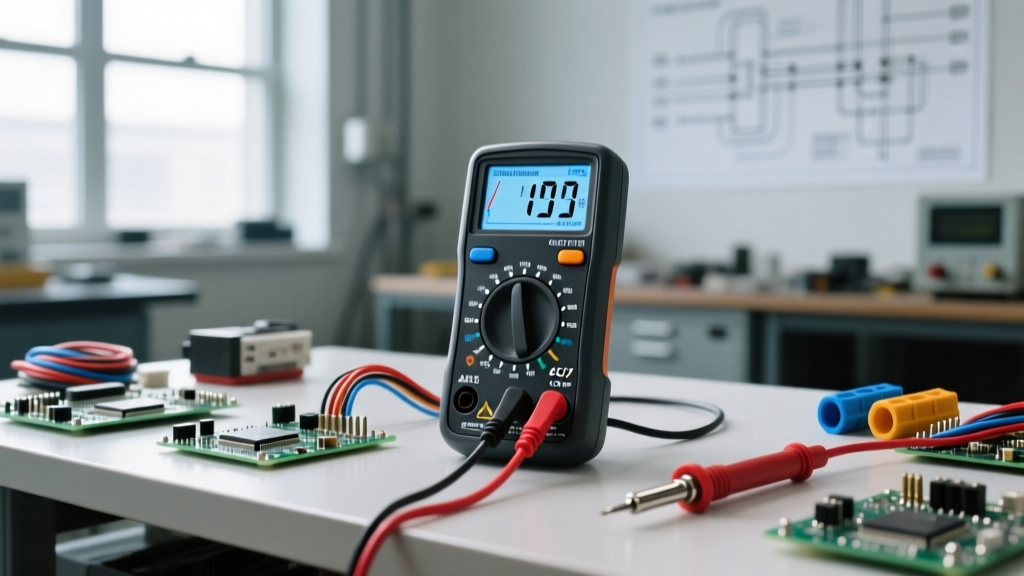
Visual inspection only gets you halfway there. Always verify your components before inserting them into a complex circuit. Set your digital multimeter to the Diode Test mode (usually indicated by a triangle and line symbol). Touch the red probe to the anode and black to the cathode of an LED; a healthy LED will glow faintly and display a forward voltage drop between 1.8V and 3.3V on the screen. If it reads 'OL' (Open Loop) in both directions, the internal wire bond has snapped, and the component is dead.