
The Foundation of Electronics Troubleshooting
Learning the art of testing electronic components is not a single skill, but a progressive journey. Beginners often treat a multimeter as a simple pass/fail buzzer, while seasoned engineers use dynamic signal analysis to uncover intermittent, heat-dependent, or frequency-specific failures. Whether you are repairing a vintage audio amplifier or debugging a custom ESP32 PCB, a structured approach prevents misdiagnosis and saves hours of frustrating rework.
This guide outlines a definitive skill-building path, taking you from foundational continuity checks to advanced in-circuit impedance analysis. By mastering these three tiers, you will transition from guessing to diagnosing with absolute certainty.
Level 1: Passive Component & Continuity Basics (Beginner)
The first tier focuses on out-of-circuit testing of passive components and basic circuit paths. At this stage, your primary tool is a reliable, auto-ranging digital multimeter (DMM) with a fast continuity beeper. A popular, budget-friendly choice for this tier is the Klein Tools MM400 (retailing around $45), which offers adequate accuracy (±0.7% DC) for basic passive checks.
Mastering Resistance and Continuity
Novices frequently confuse continuity with low resistance. Continuity simply asks, "Is the resistance below a specific threshold (usually 30-50Ω)?" Resistance asks, "What is the exact opposition to current flow?"
- Resistors: Always test resistors out of circuit. Parallel paths on a PCB will artificially lower your reading. A 10kΩ resistor with a 5% tolerance should read between 9.5kΩ and 10.5kΩ. If it reads 12kΩ, the carbon film has degraded due to thermal stress.
- Fuses and Switches: Use the continuity setting. A good fuse reads near 0.0Ω. If a glass cartridge fuse reads open (OL), inspect the interior. A clean break indicates a slow overload; a blackened, shattered interior indicates a catastrophic short circuit.
- PCB Traces: When checking for broken traces, use the "relative" (REL) mode on your DMM to zero out the resistance of your test leads, which can skew readings on low-ohm shunt resistors.
Pro-Tip: Never measure resistance on a live circuit. The presence of external voltage will corrupt the DMM's internal current source, yielding false readings and potentially blowing the multimeter's internal protection fuse.
Level 2: Semiconductor & Capacitance Diagnostics (Intermediate)
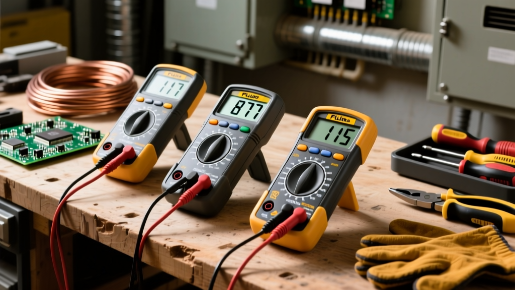
As you progress, you must evaluate non-linear components like diodes, transistors, and capacitors. This requires a DMM with dedicated semiconductor testing modes and capacitance measurement. The Fluke 117 True-RMS Multimeter (approximately $200) is the industry standard here, featuring a dedicated diode test mode and VoltAlert non-contact voltage detection.
The Diode Test Mode: Why Resistance Fails
Testing a diode with the standard ohms (Ω) setting is a critical beginner mistake. Resistance mode applies an arbitrary voltage and measures current, which varies wildly between multimeter brands. Instead, use the Diode Test mode. As detailed in Fluke's official diagnostic guidelines, this mode sources a known constant current (usually 1-2mA) and measures the resulting forward voltage drop across the PN junction.
- Silicon Diodes (e.g., 1N4148, 1N4007): Expect a forward voltage drop between 0.500V and 0.800V. Reverse bias should read "OL" (Open Loop).
- Schottky Diodes (e.g., 1N5819): Expect a lower forward drop, typically 0.200V to 0.400V, due to the metal-semiconductor junction.
- LEDs: Standard red/green LEDs will show a 1.8V to 2.2V drop and faintly illuminate. Blue and white LEDs require >3V to turn on, which may exceed your DMM's test voltage, resulting in an "OL" reading even if the LED is perfectly functional.
Capacitor Health: Beyond Simple Capacitance
Electrolytic capacitors are the most common failure point in power supplies. While a DMM can measure capacitance (in microfarads, µF), it cannot detect Equivalent Series Resistance (ESR). A 1000µF capacitor might still read 980µF on a DMM but possess an ESR of 15Ω due to dried-out internal electrolyte, rendering it useless for high-frequency ripple filtering. For accurate ESR testing, you must advance to Level 3 tools.
Level 3: In-Circuit & Dynamic Signal Testing (Advanced)
Advanced diagnostics involve testing components while they remain soldered to the board (in-circuit) and analyzing their behavior under dynamic AC conditions. This tier requires an LCR meter and an oscilloscope.
LCR Meter Impedance Analysis
The DER EE DE-5000 LCR Meter (around $120) is a phenomenal bench tool. Unlike a DMM, an LCR meter tests components using specific AC frequencies (100Hz, 1kHz, 100kHz). This is vital because ceramic and electrolytic capacitors exhibit different capacitance values depending on the test frequency.
- Testing Inductors: Test at 1kHz or 100kHz to measure inductance (L) and the Quality Factor (Q). A low Q-factor indicates high internal winding resistance or core losses.
- ESR Measurement: Set the LCR meter to 100kHz to measure the ESR of electrolytic capacitors in-circuit. An ESR above 1.0Ω in a 100µF+ power supply filter cap usually mandates replacement.
Oscilloscope Curve Tracing & Dynamic Probing
For active components like MOSFETs and ICs, static multimeter tests are insufficient. A MOSFET might pass a diode test on its body diode but still suffer from gate-oxide puncture due to Electrostatic Discharge (ESD). Using an entry-level scope like the Rigol DS1054Z (~$350), you can monitor the gate-to-source voltage (Vgs) during switching. If the gate drive signal shows severe ringing or fails to reach the threshold voltage (typically 2V-4V for logic-level MOSFETs), the component or its driver IC is failing under load.
Component Testing Quick-Reference Matrix
Use this matrix as a quick-reference cheat sheet when approaching an unknown PCB fault. For deeper foundational theory on multimeter operation, refer to the comprehensive SparkFun Multimeter Tutorial.
| Component | Primary Tool | Test Mode / Setting | Expected Healthy Reading | Common Failure Signature |
|---|---|---|---|---|
| Carbon Film Resistor | DMM | Resistance (Ω) | Within ±5% of color code | Reads 20%+ high (thermal drift) |
| Rectifier Diode | DMM | Diode Test | 0.5V - 0.8V Forward / OL Reverse | Shorted (0.0V both ways) or Open |
| N-Channel MOSFET | DMM | Diode Test (Body Diode) | 0.4V - 0.6V (Drain to Source) | Shorted D-S (gate oxide puncture) |
| Electrolytic Capacitor | LCR Meter | ESR @ 100kHz | < 0.5Ω (varies by capacity) | ESR > 2.0Ω (electrolyte dry-out) |
| Power Inductor | LCR Meter | Inductance (L) @ 1kHz | Matches schematic value (µH/mH) | Open circuit (winding break) |
The "Half-Split" Troubleshooting Framework
Knowing how to test a component is only half the battle; knowing where to test is the other. When facing a complex board failure, employ the Half-Split Method.
- Identify the signal or power path from input to output.
- Probe the exact electrical midpoint of the circuit.
- If the midpoint is healthy, the fault lies in the second half. If dead, the fault lies in the first half.
- Repeat the split on the faulty half until you isolate the specific failing node or component.
This binary search algorithm drastically reduces the number of components you need to desolder and test, minimizing thermal damage to the PCB pads and saving valuable diagnostic time.
Safety and Handling Best Practices
Before testing sensitive semiconductors, always ground yourself. As noted by the ESD Association, human body model (HBM) static discharges as low as 30 volts can permanently degrade the internal silicon junctions of modern ICs and MOSFETs, leading to "walking wounded" components that pass bench tests but fail unpredictably in the field. Always use an ESD wrist strap connected to a verified earth ground when handling raw components outside of anti-static packaging.
Summary of Your Path Forward
Testing electronic components effectively requires matching the right tool to the specific physics of the part. Start by mastering continuity and basic resistance with a reliable DMM. Graduate to semiconductor junction analysis using dedicated diode test modes. Finally, invest in LCR and oscilloscope equipment to evaluate dynamic impedance and high-frequency behavior. By following this structured skill-building path, your diagnostic accuracy will evolve from guesswork to precision engineering.