
The Modern Reality of Electronic Components Identification
As surface-mount technology (SMT) continues to shrink, with 0201 metric (0603 imperial) and even 01005 imperial packages becoming standard in consumer and IoT devices, visual electronic components identification has evolved from a simple glance to a forensic science. Whether you are reverse-engineering a legacy motherboard, repairing a modern drone flight controller, or prototyping a mixed-signal PCB, accurately identifying passives, semiconductors, and integrated circuits is the critical first step in any diagnostic workflow.
This guide bypasses generic textbook theory and dives straight into the practical, field-tested methodologies used by PCB repair technicians and hardware engineers to identify components accurately, decode cryptic SMD markings, and recognize visual failure signatures.
Decoding Passive Components: Beyond the Color Bands
While through-hole resistors with their 4-band or 5-band color codes remain common in power supplies and hobbyist kits, modern high-density PCBs rely almost exclusively on SMD passives. Identifying these requires a firm grasp of industry coding standards.
SMD Resistor Codes and the EIA-96 Standard
Standard 5% tolerance SMD resistors use a simple 3-digit or 4-digit numerical code (e.g., 103 = 10 × 10³ = 10 kΩ). However, precision 1% tolerance resistors in 0603 and larger packages frequently use the EIA-96 coding system. This system uses two digits to represent the significant figures and a single letter for the multiplier. For a comprehensive breakdown of standard resistor color codes and basic SMD markings, the SparkFun Resistor Tutorial remains an excellent foundational reference.
| EIA-96 Code | Significant Digits (Lookup) | Multiplier Letter | Calculated Value |
|---|---|---|---|
| 01C | 01 = 100 | C = 10² | 10 kΩ |
| 68X | 68 = 499 | X = 10⁻¹ | 49.9 Ω |
| 22H | 22 = 165 | H = 10⁴ | 1.65 MΩ |
| 47A | 47 = 301 | A = 10⁰ | 301 Ω |
Pro Tip: When dealing with unmarked 0402 or 0201 metric resistors, visual identification is impossible. You must desolder one leg and measure with a high-precision multimeter or an LCR meter like the Der EE DE-5000 to avoid parallel circuit resistance skewing your reading.
Capacitor Dielectrics and Visual Identification
Multilayer Ceramic Capacitors (MLCCs) are notoriously difficult to identify once removed from their tape reels, as most are completely unmarked. Identification relies on physical size, color, and application context:
- C0G/NP0 Dielectrics: Often slightly off-white or creamy. Used in RF and timing circuits due to zero temperature coefficient.
- X7R / X5R Dielectrics: Typically a uniform tan or brown. Used for general decoupling and bulk bypass.
- Tantalum Capacitors: Easily identified by their molded rectangular epoxy bodies (often yellow, black, or orange) with a distinct polarity stripe indicating the anode (+). Warning: Installing these in reverse polarity results in catastrophic thermal failure.
Semiconductor Discretes: Diodes and Transistors in the Wild
Discrete semiconductors present a unique challenge in electronic components identification because multiple entirely different devices can share the exact same physical package.
The SOT-23 Transistor Pinout Dilemma
The SOT-23 package is the undisputed king of small-signal transistors and MOSFETs. However, a SOT-23 could house an NPN BJT, a PNP BJT, an N-channel MOSFET, or even a dual-diode pair. The silkscreen on the PCB is your best clue (e.g., 'Q' for transistor, 'D' for diode), but when silkscreen is absent, you must rely on the component's internal junctions.
Field Technique: Identifying BJT Pinouts with a Fluke 87V
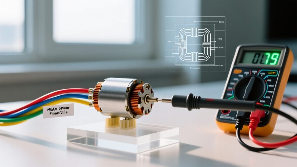
Set your multimeter to Diode Test mode. For an NPN transistor, place the red probe on the Base pin and the black probe on the Emitter and Collector. You should read a forward voltage drop of roughly 0.600V to 0.700V. Reversing the probes should yield an 'OL' (open loop) reading. PNP transistors will show the exact opposite polarity. For an in-depth guide on junction testing, refer to the Fluke official transistor testing guide.
Diode Packages and JEDEC Standards
Diodes are generally categorized by their JEDEC standard prefixes. The 1N prefix (e.g., 1N4148, 1N5819) denotes a single junction device. In SMD form, you will frequently encounter the SOD-323 and SOD-123 packages. The cathode (negative) side is always marked with a distinct band. Schottky diodes (like the BAT54 series) will show a much lower forward voltage drop (0.2V - 0.3V) on a multimeter compared to standard silicon rectifiers (0.6V).
Integrated Circuits (ICs): Logos, Lasers, and Date Codes
Identifying ICs requires a magnified eye and an understanding of manufacturer marking schemes. Modern microcontrollers, power management ICs (PMICs), and operational amplifiers rarely have enough surface area for full part numbers.
Decoding the Top Mark
A typical IC top mark contains three vital pieces of information:
- Manufacturer Logo: Identifies the fab house (e.g., Texas Instruments, STMicroelectronics, Microchip, NXP).
- Product/Traceability Code: A shortened alphanumeric string that maps to the actual part number via the manufacturer's marking lookup tool.
- Date Code: Usually a 4-digit YYWW (Year/Week) format. For example,
2435means the 35th week of 2024. This is crucial for identifying components affected by specific manufacturer silicon errata or batch recalls.
For standardized package dimensions and pin-1 indicator conventions, hardware engineers rely on JEDEC solid-state outlines, which dictate everything from QFN thermal pad sizes to BGA ball grid arrays.
Optical Tools for Micro-Marking
In 2026, laser-etched markings on 2x2mm QFN packages are incredibly faint. To accurately read these without damaging the component, technicians use polarized HDMI microscopes. The Andonstar AD407 (priced around $280) or the Plugable USB2-OTG150X are industry favorites. Using a polarizing filter on the lens eliminates the glare from the epoxy casing, revealing the laser-etched silicon trace codes hidden beneath the surface reflection.
Visual Failure Analysis: What Dead Components Look Like
Part of electronic components identification is recognizing when a component has failed. A trained eye can spot a dead component before a single probe touches the board.
| Component Type | Visual Failure Signature | Electrical Failure Mode & Root Cause |
|---|---|---|
| Tantalum Capacitor | Charred epoxy, cracked casing, burn marks on PCB | Dead short. Often caused by reverse polarity or voltage spikes exceeding the rated DC bias. |
| MLCC (X7R/X5R) | Micro-fractures near the PCB pad, visible only under 40x magnification | Intermittent short or high leakage. Root cause is mechanical board flex (piezoelectric stress cracking). |
| Electrolytic Capacitor | Bulging top vent, crusty brown electrolyte leaked onto PCB | High ESR, severe loss of capacitance. Caused by thermal degradation of the internal liquid electrolyte over time. |
| Power MOSFET | Visible pitting or hole in the plastic/epoxy casing near the drain pin | Drain-to-Source short. Usually the result of thermal runaway or avalanche energy exceedance. |
Essential Tools for the Identification Workbench
To execute proper electronic components identification in a modern lab, you need more than just a magnifying glass. Ensure your bench includes:
- True-RMS Multimeter: A Fluke 87V or Brymen BM869s for accurate diode testing and resistance measurements down to 0.01Ω.
- LCR Meter: The Der EE DE-5000 or Keysight U1733C. Essential for identifying unmarked inductors and verifying capacitor dielectric health via Dissipation Factor (Df) readings.
- Digital Microscope: A minimum of 1080p resolution with a ring light and polarizing filter to read SOT-23 and QFN silkscreen without glare.
- Component Tester: Devices like the TC1 or Mega328 transistor testers are excellent for quickly identifying the pinout and type (NPN/PNP/JFET/MOSFET) of scavenged, unmarked discrete semiconductors.
Mastering component identification is an iterative process. By combining optical inspection, standardized coding knowledge, and precise electrical measurement, you can confidently decode any PCB, regardless of how densely packed or poorly documented it may be.