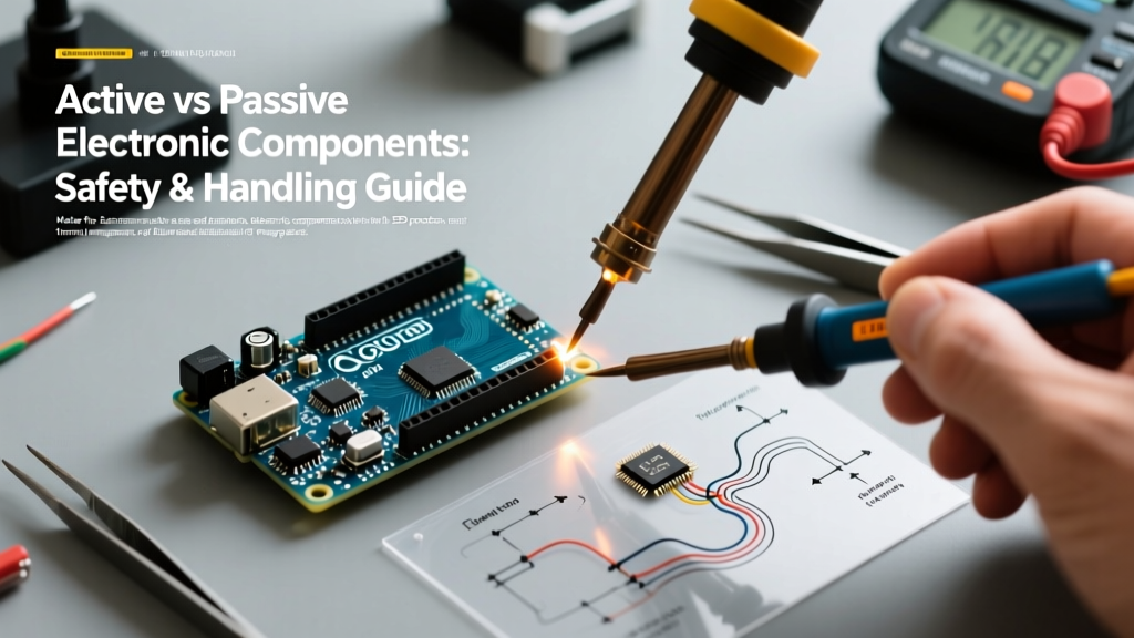

The Fundamental Divide: Energy Control vs. Energy Storage
When designing or assembling printed circuit boards (PCBs) in 2026, understanding the distinction between active and passive electronic components is not just an academic exercise—it is a critical safety requirement. While passive components (resistors, capacitors, inductors) cannot amplify signals or control current flow using an external power source, they store and dissipate energy in ways that present unique physical hazards. Active components (transistors, integrated circuits, microcontrollers), on the other hand, require external power to operate and are highly vulnerable to electrostatic discharge (ESD) and thermal runaway.
Mishandling either category can lead to catastrophic field failures, latent defects, or even personal injury. This guide details the specific safety protocols, failure modes, and best practices required when working with both active and passive electronic components in modern DIY and professional environments.
Passive Component Safety: Hidden Hazards in 'Simple' Parts
Because passive components lack semiconductor junctions, they are often mistakenly viewed as indestructible. In reality, their energy storage and dissipation characteristics demand strict adherence to safety margins.
Capacitors: Dielectric Breakdown and Venting
Aluminum electrolytic capacitors are essentially small batteries that store significant energy. If subjected to reverse polarity or overvoltage, the internal electrolyte boils, generating rapid gas expansion.
- Vent Clearance: Modern capacitors (e.g., Nichicon UHE or Kemet A700 series) feature scored pressure relief vents on the top casing (usually a cross or 'K' shape). Never solder these with the vent facing a sealed enclosure or tight plastic housing. Always maintain a minimum 3mm to 5mm vertical clearance above the vent to allow safe gas expulsion.
- Discharge Protocols: Large power supply capacitors (e.g., 400V, 470µF) can retain lethal charges for weeks. Before handling, safely discharge them using a high-wattage bleeder resistor (e.g., a 10kΩ, 5W wirewound resistor) attached to an insulated probe. Never short them with a metal screwdriver, which can vaporize the tool's tip and destroy the capacitor's internal foil.
MLCC Flex Cracking: The Silent PCB Killer
Multi-Layer Ceramic Capacitors (MLCCs) are ubiquitous but mechanically brittle. The most common failure mode in 0805 and 1206 surface-mount MLCCs is flex cracking, caused by mechanical stress during board depanelization or chassis mounting.
Safety & Layout Rule: Always place MLCCs at least 2mm away from V-score lines, mouse bites, or board edges. For high-reliability 2026 designs, specify 'soft-termination' MLCCs (e.g., TDK C-Series with Flexiterm) which incorporate a conductive epoxy layer to absorb mechanical strain without fracturing the ceramic dielectric.
Resistors: Power Derating and Thermal Hotspots
Resistors convert electrical energy into heat. A common safety oversight is running a standard 1/4W (0.25W) carbon film resistor at its absolute maximum rating. At 70°C ambient temperature, the power rating must be derated. For high-heat environments, upgrade to 1W or 2W metal oxide film resistors, which operate safely at higher surface temperatures and are inherently flameproof.
Active Component Safety: ESD, Latch-up, and Thermal Runaway
Active components rely on precisely doped semiconductor junctions and ultra-thin insulating layers. These microscopic structures are incredibly fragile and require stringent handling protocols.
ESD Vulnerability in MOSFETs and ICs
The gate oxide layer in a modern power MOSFET (like the Vishay Si2302 or Infineon OptiMOS series) is often less than 20 nanometers thick. A human body can easily accumulate 3,000V to 5,000V of static electricity just by walking across a synthetic carpet. According to the ESD Association, a discharge of just 30V is enough to puncture the gate oxide of a highly sensitive component, causing immediate or latent failure.
- Grounding: Always wear a grounded ESD wrist strap containing an inline 1MΩ safety resistor (to protect the user from mains shock if a fault occurs).
- Workstation Setup: Use a dissipative ESD mat (10^6 to 10^9 ohms/sq) connected to a common ground point. Never place bare ICs on standard plastic bags or Styrofoam, which are highly triboelectric (charge-generating) materials.
- Ionization: For environments with low humidity (<30%), use an ESD ionizer fan to neutralize static charges on non-conductive surfaces like PCB substrates.
Thermal Management for Power Semiconductors
Active components like voltage regulators (e.g., LM317 in a TO-220 package) or power transistors (TIP120) generate immense localized heat. The TO-220 package can safely dissipate only about 1.5W to 2.0W in free air before the silicon junction reaches its 150°C thermal shutdown or destruction limit.
- Thermal Interface Materials (TIM): Never mount a TO-220 directly to a bare aluminum heatsink without a TIM. Use a 0.15mm thick thermal pad (e.g., Bergquist Sil-Pad 900S) or a thin, even layer of thermal grease.
- Mounting Torque: The mounting screw for a TO-220 package should be torqued to exactly 0.6 Nm (approx. 5.3 in-lbs). Overtightening cracks the epoxy header; undertightening creates air gaps that cause thermal runaway.
Wide Bandgap Semiconductors: GaN and SiC Handling
In 2026, Gallium Nitride (GaN) and Silicon Carbide (SiC) active components are standard in high-efficiency power supplies. GaN HEMTs (like the EPC2045) have ultra-low gate threshold voltages (often ~1.4V). They are highly susceptible to dv/dt induced parasitic turn-on. Safety best practice dictates using a gate driver capable of delivering a negative turn-off voltage (e.g., -3V) to keep the device securely in the off-state during high-speed switching transients.
Handling & Assembly Best Practices Matrix
The following matrix outlines the distinct safety and handling requirements when comparing active vs passive electronic components on the workbench.
| Parameter | Passive Components (Caps, Resistors, Inductors) | Active Components (ICs, MOSFETs, Diodes) |
|---|---|---|
| ESD Sensitivity | Generally immune (except some high-Q RF inductors/tantalums) | Extremely high (HBM and CDM sensitive) |
| Primary Physical Hazard | Explosion/venting (electrolytics), thermal burns (power resistors) | Silicon thermal runaway, package delamination, toxic outgassing if overheated |
| Moisture Sensitivity | Low (MSL 1 usually); baking rarely required | High (MSL 2 to 6); requires dry-box storage and pre-baking |
| Mechanical Fragility | High for ceramic caps (flex cracking); low for axial resistors | High for fine-pitch BGA/QFN leads; silicon die cracking from overtightening |
| Storage Requirement | Standard dry room temperature | ESD-shielded bags, nitrogen dry cabinets (<5% RH for MSL 3+) |
Soldering Profiles and Moisture Sensitivity Levels (MSL)
Active components, particularly surface-mount ICs in QFP or BGA packages, absorb moisture from the ambient air. When exposed to reflow soldering temperatures (240°C to 260°C for lead-free SAC305 solder), this trapped moisture vaporizes instantly, causing the 'popcorn effect'—where the internal steam pressure delaminates the plastic package and cracks the silicon die.
According to reliability data from the NASA Electronic Parts and Packaging (NEPP) Program, strictly adhering to Moisture Sensitivity Levels (MSL) is non-negotiable for aerospace and high-reliability active components.
- MSL 1 & 2: Can generally be soldered without pre-baking if the factory seal is intact.
- MSL 3 to 6: If the humidity indicator card (HIC) in the ESD bag shows >10% saturation, the active components must be baked at 125°C for 8 to 24 hours (depending on package thickness) before reflow.
- Passive Soldering: MLCCs are prone to thermal shock. When hand-soldering, never apply a 400°C iron tip directly to the ceramic body. Heat the PCB pad first, then feed the solder, allowing capillary action to draw the heat into the component termination. For more on basic static and thermal safety, refer to foundational guides like those provided by SparkFun Electronics.
Summary: Building a Safety-First Mindset
Understanding the dichotomy of active vs passive electronic components is the foundation of reliable and safe electronics work. Passives demand respect for stored energy and mechanical stress limits, while actives require rigorous ESD protection and thermal management. By implementing proper derating, utilizing correct TIMs, and respecting MSL baking protocols, you eliminate the vast majority of latent defects and ensure your 2026 DIY projects and professional prototypes operate safely for their entire designed lifespan.