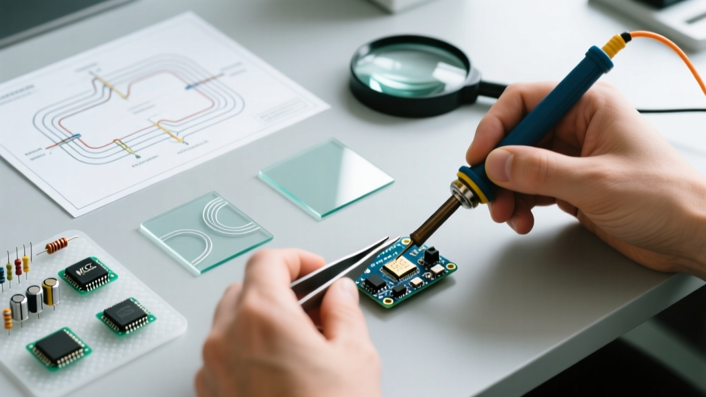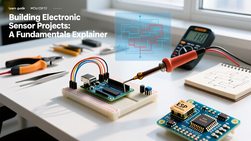

Designing reliable electronic sensor projects requires more than just copying a wiring diagram from a forum. Whether you are building an automated greenhouse climate controller or a high-speed telemetry logger for a drone, the difference between a prototype that works on a desk and a deployment that survives the real world comes down to signal integrity, power stability, and protocol management. In 2026, with the ESP32-S3 and RP2040 serving as the baseline microcontrollers for most DIY and prosumer builds, understanding the physical and electrical fundamentals of sensor integration is critical.
The Core Taxonomy: Analog, Digital, and Protocol-Based Sensors
Before wiring a single jumper cable, you must classify your sensor's output type. Misidentifying a sensor's signaling method is the leading cause of fried GPIO pins and corrupted data.
1. Analog Sensors (Continuous Voltage)
Sensors like Light Dependent Resistors (LDRs), NTC thermistors, and basic soil moisture probes output a continuous voltage or variable resistance. To read these, your microcontroller's Analog-to-Digital Converter (ADC) must translate the voltage into a discrete number.
- Resolution Matters: A classic Arduino Uno offers a 10-bit ADC (0-1023 values), meaning each step on a 5V scale represents ~4.88mV. Modern boards like the ESP32-S3 feature a 12-bit ADC (0-4095 values), but it suffers from non-linearity at the extreme ends of the 0-3.3V range. For precision analog sensor projects, bypass the internal ADC and use an external I2C ADC like the ADS1115 (~$4.50), which provides 16-bit resolution and a programmable gain amplifier.
2. Discrete Digital & 1-Wire Sensors
Sensors like the DS18B20 (waterproof temperature probe) use proprietary digital protocols over a single data wire. Unlike analog sensors, they require a specific 4.7kΩ pull-up resistor connected between the data line and VCC to hold the bus high when idle. Omitting this resistor results in floating pins and erratic readings.
3. Protocol-Based Sensors (I2C, SPI, UART)
Advanced environmental and motion sensors—such as the Bosch BME280 (temperature, humidity, pressure) or the InvenSense MPU6050 (6-axis IMU)—communicate via standardized digital buses. The BME280 is a staple in 2026 electronic sensor projects due to its high accuracy and low power draw, typically costing between $8 and $12 for a quality breakout board.
Communication Protocol Matrix
Choosing the right protocol dictates your wiring complexity and data throughput. Use this matrix to select the appropriate bus for your specific sensor array.
| Protocol | Wires Required | Max Speed (Typical) | Topology | Best Use Case |
|---|---|---|---|---|
| I2C | 2 (SDA, SCL) | 400 kHz (Fast) / 1 MHz (Fast+) | Multi-master, Multi-slave (Address-based) | Low-speed environmental sensors, OLED displays, chaining multiple sensors on limited GPIO. |
| SPI | 4 (MOSI, MISO, SCK, CS) | 10 MHz - 50 MHz+ | Single-master, Multi-slave (Chip Select) | High-speed data (SD cards, TFT screens, high-sample-rate ADCs). |
| UART | 2 (TX, RX) | 115200 bps (Standard) / 3 Mbps | Point-to-Point | GPS modules, cellular modems, fingerprint scanners. |
| 1-Wire | 1 (Data/Power) | 15.4 kbps | Multi-drop (ROM Address) | Distributed temperature sensing (DS18B20 arrays). |
Critical Wiring Rules for Sensor Integration
Even the most expensive sensors will fail if the underlying physical layer is compromised. Adhere to these three non-negotiable wiring rules.
Rule 1: Logic Level Matching (The 3.3V vs. 5V Trap)
Most modern microcontrollers (ESP32, Raspberry Pi Pico, STM32) operate at 3.3V logic. However, many legacy sensors and displays still require 5V logic. Connecting a 5V sensor output directly to a 3.3V microcontroller GPIO will permanently degrade or destroy the silicon.
Expert Tip: Never rely on internal microcontroller clamping diodes to handle continuous 5V overvoltage. For bidirectional I2C level shifting, use a breakout board based on the BSS138 MOSFET or the TXS0108E IC. These cost roughly $1.50 to $3.00 and safely translate voltage domains without corrupting I2C rise times.
Rule 2: Mandatory Decoupling Capacitors
Sensors draw transient current spikes when taking a measurement or transmitting data. If your power traces have high impedance, this causes localized voltage drops, resetting the sensor or corrupting I2C packets. Always place a 100nF (0.1µF) ceramic capacitor as physically close to the sensor's VCC and GND pins as possible. For high-current sensors like ultrasonic rangers (e.g., HC-SR04), add a bulk 10µF electrolytic capacitor in parallel.
Rule 3: Managing I2C Bus Capacitance
According to the NXP I2C Bus Specification, the maximum allowed bus capacitance is 400pF. Long wires act as capacitors. If you run I2C wires longer than 30cm to a remote sensor, the signal edges will slope, causing the microcontroller to miss clock pulses. For long-distance electronic sensor projects, switch to SPI, use RS-485 transceivers, or deploy an I2C bus extender like the PCA9600.
Troubleshooting Edge Cases and Failure Modes
When your code compiles but the sensor returns NaN (Not a Number) or hangs the microcontroller, use this targeted troubleshooting workflow. A reliable digital multimeter is your primary diagnostic tool; refer to the Fluke continuity testing guide to verify physical trace connections before assuming a software bug.
- Verify Power Rails Under Load: Measure VCC and GND at the sensor's physical pins, not at the microcontroller. A reading of 2.9V on a 3.3V rail indicates undersized wiring or a failing voltage regulator.
- Scan for I2C Address Collisions: If you are using two identical sensors (e.g., two MPU6050 IMUs), they share the same default I2C address (0x68). The bus will lock up. Solution: Use an I2C multiplexer like the TCA9548A ($3-$5), which allows you to route the bus to 8 separate channels, isolating conflicting addresses.
- Check Pull-Up Resistor Sizing: If I2C data is corrupted at 400kHz but works at 100kHz, your pull-up resistors are too weak (too high in ohms) to pull the bus high quickly enough. Drop from 10kΩ to 4.7kΩ or even 2.2kΩ for faster rise times, as detailed in Analog Devices' I2C protocol guidelines.
- Isolate Ground Loops: If mixing motors and sensitive analog sensors, motor EMI will inject noise into the analog ground. Use star-grounding topologies or digital isolators (like the ISO1540) to separate noisy power domains from sensor logic.
Summary: Building for Reliability
Successful electronic sensor projects bridge the gap between software logic and physical electronics. By respecting logic voltage thresholds, managing bus capacitance, and implementing proper decoupling, you eliminate 90% of the hardware bugs that plague beginner builds. Always prototype with modular breakout boards, validate your physical layer with a multimeter and oscilloscope, and only then commit to a custom printed circuit board (PCB) layout.