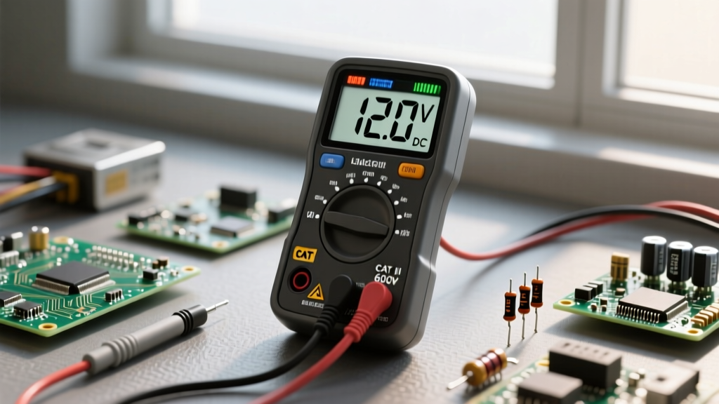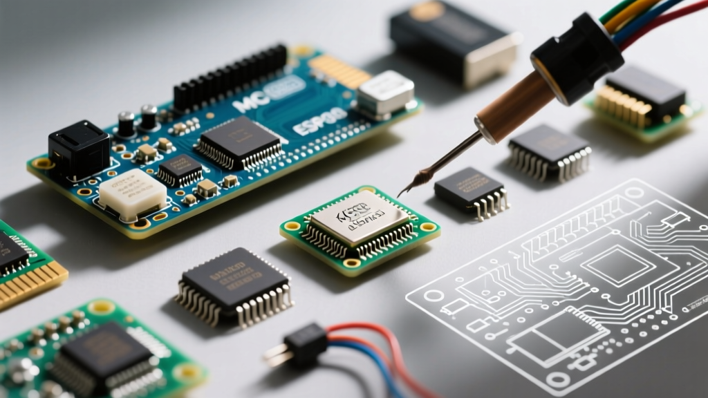

The Anatomy of Fake Silicon: Why Counterfeit Electronic Components Matter
The global supply chain for semiconductors and passive components remains under immense pressure in 2026, creating a lucrative shadow market for counterfeit electronic components. From cloned STM32 microcontrollers with mismatched flash memory to re-tinned, e-waste-harvested LM317 voltage regulators, fake parts introduce catastrophic failure modes into aerospace, medical, and consumer electronics. According to the SAE International AS5553C standard, counterfeit parts are not just clones; they include uprated, downrated, or salvaged components misrepresented as new, factory-traceable inventory.
As a hardware engineer, lab technician, or procurement specialist, relying solely on distributor packaging is no longer sufficient. This comprehensive reference guide and cheat sheet provides actionable, deep-level testing protocols to verify component authenticity before they ever touch your SMT pick-and-place machine or breadboard.
Level 1: Visual Inspection Cheat Sheet (Non-Destructive)
Visual inspection under a 10x to 40x stereomicroscope (such as the AmScope SE400-Z) is your first line of defense. Counterfeiters often rely on 'blacktopping'—sanding down the original laser marks and applying a new layer of black epoxy to stamp fake part numbers. Here is exactly what to look for:
Package Dimensions and Chamfers
- Caliper Verification: Use a Mitutoyo digital caliper (resolution 0.01mm) to measure the package length, width, and thickness. Compare these against the manufacturer's mechanical datasheet. A deviation of >0.15mm often indicates a cloned or salvaged package.
- Corner Chamfers and Orientation Dimples: Factory-molded ICs have precise, sharp corner chamfers and deep, cleanly machined Pin 1 indicator dimples. Counterfeits often feature shallow, asymmetrical dimples or rounded, hand-filed corners.
- Mold Flash and Ejector Pins: Inspect the top and bottom surfaces for circular ejector pin marks. Genuine parts have uniform, flush ejector marks. Fake or re-molded parts often show raised 'flash' or uneven circular depressions.
Lead Coplanarity and Oxidation
- The Coplanarity Test: Place the IC on a perfectly flat optical glass surface. Look for light leaking under the pins. Genuine SMD components have a coplanarity of less than 0.08mm. Salvaged parts that were pulled from donor boards and re-tinned will rock or show bent leads.
- Solder Meniscus and Re-tinning: Examine the leads under high magnification. Factory tinning stops precisely at the package body. Salvaged parts exhibit a 'solder meniscus'—solder creeping up the lead toward the plastic body. Furthermore, re-tinned leads often look overly glossy and lack the micro-crystalline matte texture of fresh factory lead-free (RoHS) finishes.
Level 2: Chemical and Optical Verification
When visual anomalies are subtle, chemical and optical tests expose the physical tampering used to disguise salvaged or downgraded chips.
The Solvent Wipe Test (Acetone and MEK)
Blacktopping relies on aftermarket epoxy or paint that lacks the chemical resilience of factory-molded epoxy novolac resins.
- Soak a lint-free foam swab in high-purity Acetone or Methyl Ethyl Ketone (MEK).
- Rub the top surface of the IC firmly for 30 to 60 seconds.
- Pass: The swab remains clean, and the laser etching remains crisp.
- Fail: The swab picks up black or gray residue, revealing the original part number or a blank, sanded silicon surface underneath.
UV Fluorescence Analysis
Shine a 365nm UV flashlight onto the IC package. Genuine mold compounds contain specific fillers that exhibit a uniform, dull fluorescence (or none at all). The aftermarket epoxy used for blacktopping often contains optical brighteners or different curing agents that fluoresce brightly or show splotchy, uneven patterns under UV light, clearly outlining the sanded boundaries.
Level 3: Advanced Internal Imaging (X-Ray and CSAM)
For high-reliability applications, non-destructive internal imaging is mandated by NASA NEPP guidelines for critical flight hardware.
X-Ray Inspection
Using a system like the Nikon XT V 160, X-ray imaging reveals the internal architecture of the component without breaking the seal.
- Die Size and Orientation: Compare the X-ray silhouette of the silicon die against a Known Good Component (KGC). Counterfeiters often put a smaller, cheaper die (e.g., an op-amp with lower bandwidth) into a larger package.
- Bond Wire Sweep: Genuine automated wire bonding creates perfect, symmetrical loops. Salvaged parts that have been subjected to unauthorized reflow baking often show 'bond wire sweep'—wires that have shifted or shorted internally due to thermal stress.
CSAM (Confocal Scanning Acoustic Microscopy)
CSAM uses high-frequency ultrasound to detect internal voids. If a chip has been blacktopped, the acoustic impedance mismatch between the original mold compound and the new topcoat will create a bright, distinct reflection line. CSAM also detects internal delamination caused by improper moisture baking of salvaged e-waste parts.
Level 4: Destructive Testing (Decapsulation)
When absolute certainty is required, decapsulation ('decap') exposes the bare silicon die. This process destroys the component but provides irrefutable proof of authenticity.
Safety Warning: Decapsulation requires fuming Nitric Acid (HNO3) or concentrated Sulfuric Acid (H2SO4). This must only be performed in a certified chemical fume hood with full PPE, including acid-resistant aprons and face shields.
The Hot Acid Decap Procedure
- Place the IC in a glass beaker and cover with fuming Nitric Acid.
- Heat the acid to approximately 80°C - 120°C on a hot plate. The acid will aggressively dissolve the epoxy mold compound while leaving the silicon die and metallic bond wires intact.
- Once the die is exposed, neutralize and rinse with deionized (DI) water.
- Inspect the die under a metallurgical microscope at 100x to 500x magnification.
What to Look For on the Bare Die
- Die Markings: Genuine silicon features laser-etched or electron-beam etched logos, part numbers, and revision codes directly on the silicon or passivation layer. Clones often lack these, or feature crude, misaligned photolithography.
- Bond Wire Material: Many modern cost-optimized genuine ICs use copper bond wires. If your X-ray or decap reveals gold wires on a part specified as copper (or vice versa), you likely have a counterfeit or an unauthorized die revision.
Level 5: Electrical Verification and Curve Tracing
Cloned microcontrollers and analog ICs might look identical and pass basic functional tests, but they fail under edge-case electrical stress. Using a Power Device Analyzer (like the Keysight B1505A) or a Huntron Tracker for IV curve tracing reveals the true nature of the silicon.
- Parasitic Capacitance: Cloned silicon layouts are rarely perfect 1:1 copies. They exhibit different parasitic capacitances on I/O pins, which alters high-frequency signal integrity.
- ESD Diode Forward Voltage: Measure the IV curve of the internal ESD protection diodes to ground. Genuine parts have tightly controlled forward voltage drops (e.g., 0.65V). Fakes often show erratic, soft 'knees' in the curve due to inferior doping processes.
- Quiescent Current (Iq): Cloned voltage regulators and op-amps frequently draw 2x to 5x more quiescent current than the datasheet specifies, destroying battery life in portable designs.
Component Testing Methods Matrix
| Testing Method | Equipment Required | Est. Cost (USD) | Destructive? | Primary Detection Target |
|---|---|---|---|---|
| Visual & Caliper | Stereomicroscope, Digital Caliper | $500 - $2,500 | No | Re-tinning, sanding, wrong package size |
| Solvent Wipe | Acetone/MEK, Lint-free swabs | < $50 | No | Blacktopping, fake laser markings |
| X-Ray Imaging | Micro-focus X-Ray System | $75,000+ | No | Missing die, bond wire sweep, wrong leadframe |
| Curve Tracing | Huntron Tracker, Keysight B1505A | $5,000 - $150,000 | No | Cloned silicon, altered ESD structures |
| Decapsulation | Fuming HNO3, Fume Hood, Hot Plate | $2,000 (Setup) | Yes | Die markings, photolithography quality |
Supply Chain Defense: Sourcing Framework
Detection is a reactive measure; prevention is proactive. To minimize the risk of receiving counterfeit electronic components, implement a strict procurement framework:
- Buy Authorized: Always prioritize authorized distributors (e.g., Mouser, Digi-Key, Arrow, Avnet). These suppliers have direct, audited supply lines back to the original component manufacturer (OCM).
- Vet the Gray Market: If you must source from independent brokers due to obsolescence or allocation shortages, require the supplier to provide a Certificate of Conformance (CoC) traceable directly to the OCM.
- Check the ERAI database: Before onboarding a new broker, search the Electronic Resellers Association International (ERAI) database for historical counterfeit complaints or alerts associated with that vendor.
- Mandate Incoming Inspection: For any parts sourced outside the authorized network, mandate a Level 1 and Level 2 inspection protocol (Visual + Solvent) before releasing the reels to the SMT production floor.
Summary
Counterfeiters are continuously refining their techniques, moving from simple sanding and re-stamping to sophisticated cloning of silicon wafers. By utilizing this cheat sheet—progressing from basic visual coplanarity checks and solvent wipes to advanced X-ray and destructive decapsulation—you can build an impenetrable wall between fake components and your final PCB assembly. Always trust empirical data over supplier promises, and maintain a library of Known Good Components (KGCs) for critical ICs in your designs.