
The Silent Threat: Understanding Metal Migration in Electronic Components
As surface-mount technology pushes toward ultra-fine pitches—routinely hitting 0.35mm and below in 2026's high-density interconnect (HDI) boards—the physical space between conductors has never been smaller. This miniaturization brings a critical safety and reliability hazard to the forefront: metal migration in electronic components, formally known as Electrochemical Migration (ECM).
ECM is not a theoretical edge case; it is a primary failure mode in automotive Battery Management Systems (BMS), medical life-support devices, and aerospace avionics. When ECM occurs, metallic dendrites bridge the gap between an anode and a cathode, creating a dead short. In high-power circuits, this can trigger localized thermal runaway, component combustion, or catastrophic system failure.
The Electrochemistry of Dendritic Growth
To implement effective safety practices, you must understand the ECM triad. According to extensive failure analysis research by NASA's Electronic Parts and Packaging (NEPP) Program, ECM requires three simultaneous conditions:
- Anodic Dissolution: Metal ions (e.g., Ag+, Cu2+) dissolve from the anode due to an applied voltage bias.
- Electrolytic Path: A moisture film, combined with ionic contamination (flux residue, halides, or environmental pollutants), forms a conductive bridge.
- Cathodic Deposition: Ions migrate toward the cathode, reduce to metal atoms, and precipitate into tree-like structures called dendrites.
Metal Susceptibility & Failure Matrix
Not all conductive materials migrate at the same rate. Below is a risk matrix for common PCB finishes and component metallizations encountered in modern assemblies.
| Metal / Finish | Migration Tendency | Typical Failure Environment | Primary Mitigation Strategy |
|---|---|---|---|
| Silver (Ag) | Critical / Very High | High humidity, thick-film resistors, MLCC terminations | Parylene coating, strict halide-free flux |
| Copper (Cu) | High | Bare PCB traces, micro-vias, uncoated inner layers | ENIG/OSP surface finishes, SIR testing |
| Tin (Sn) | Moderate (Whiskers vs ECM) | Matte tin finishes, high-stress mechanical environments | Conformal coating, annealing post-plating |
| Gold (Au) | Negligible | N/A (Highly noble) | Used in critical aerospace/medical pads |
Environmental Triggers and the 2026 Climate Reality
In 2026, electronic assemblies are increasingly deployed in harsh, uncontrolled environments—from outdoor 5G small cells to agricultural IoT sensors. The primary trigger for metal migration in electronic components is the formation of a microscopic water film on the PCB surface. This film requires a relative humidity (RH) threshold, typically above 75%, combined with hygroscopic contaminants.
Flux residues containing rosin or synthetic resins can absorb moisture from the air, lowering the localized RH threshold required for ECM to as low as 55%. Furthermore, thermal cycling (e.g., a solar inverter heating up during the day and cooling at night) causes 'breathing,' pulling humid air into micro-crevices under BGA packages and QFN thermal pads. Once condensation occurs, the trapped moisture combined with residual halides creates a highly aggressive, localized electrolytic cell that standard conformal coatings cannot penetrate if applied improperly.
The Hidden Danger: Silver Migration in MLCCs
Multi-Layer Ceramic Capacitors (MLCCs) utilize silver-palladium or pure silver terminations. In high-voltage DC circuits, if the PCB surface is contaminated, silver ions migrate exceptionally fast. Unlike copper dendrites, which often burn open when the short circuit carries high current, silver dendrites can sustain higher current densities and cause persistent, intermittent faults that are notoriously difficult to capture on standard oscilloscopes. This is why automotive AEC-Q200 qualified MLCCs often require specialized termination geometries and strict assembly cleanliness protocols.
Best Practices for ECM Prevention and Safety
Preventing metal migration in electronic components requires a multi-layered defense strategy spanning PCB design, assembly chemistry, and post-assembly sealing.
1. Flux Chemistry and Mandatory Cleaning
The most common catalyst for ECM is leftover flux residue. Under the IPC-J-STD-004B standard, fluxes are categorized by material type and activity level. For high-reliability 2026 applications (e.g., EV inverters operating at 800V), relying on 'No-Clean' flux is a dangerous compromise if the board will be exposed to condensing environments.
- ROL0 (Rosin, Low Activity, No Halides): The baseline for commercial no-clean. Safe for consumer electronics, but vulnerable in high-humidity automotive under-hood applications.
- Water-Soluble (ORG): Offers superior wetting for 0201 and 01005 components but must be cleaned. Leaving ORG flux residue guarantees rapid ECM.
- Cleaning Protocol: Use a saponified DI (Deionized) water wash or an engineered solvent like MicroCare's Advanced Cleaner. Verify cleanliness using a ROSE (Resistivity of Solvent Extract) test per IPC-TM-650 2.3.25, targeting an ionic equivalent of less than 1.56 µg NaCl/cm².
2. Conformal Coating: The Ultimate Physical Barrier
When environmental sealing is impossible, conformal coating starves the ECM triad of its electrolyte (moisture). However, improper application can trap contaminants against the PCB, accelerating corrosion.
Expert Safety Warning: Never apply acrylic or urethane conformal coating over uncleaned, water-soluble flux residues. The coating will trap the aggressive halides, creating a localized micro-climate that accelerates metal migration and delaminates the coating from the inside out.
Material Selection Guide:
- Acrylics (e.g., HumiSeal 1B31): Cost-effective ($0.30 - $0.60 per board), easy to rework, but offers poor chemical and solvent resistance. Best for indoor consumer IoT.
- Urethanes (e.g., Electrolube PUC): Excellent humidity resistance and chemical stability. Ideal for industrial controls. Cost: $0.80 - $1.20 per board.
- Parylene (Vapor Deposition): The gold standard for medical and aerospace. It penetrates under BGA components and forms a pinhole-free barrier at 10-25 microns. Cost: $3.00 - $8.00+ per board due to batch vacuum processing.
3. PCB Layout and Clearance Rules
Designing out the risk starts in the CAD environment. According to IPC-2221B guidelines, electrical clearance must account for the operating voltage and the environmental coating condition. For a 400V DC bus (common in modern solar inverters), uncoated inner-layer spacing requires a minimum of 1.2mm, whereas coated outer layers can safely operate at 0.8mm. Always design test coupons into your panel borders to allow for destructive cross-sectioning and Surface Insulation Resistance (SIR) testing.
Diagnostic Troubleshooting: Confirming ECM in the Field
When a field return exhibits a short circuit, distinguishing between EOS (Electrical Overstress) and ECM is critical for liability and root-cause analysis. Follow this diagnostic workflow:
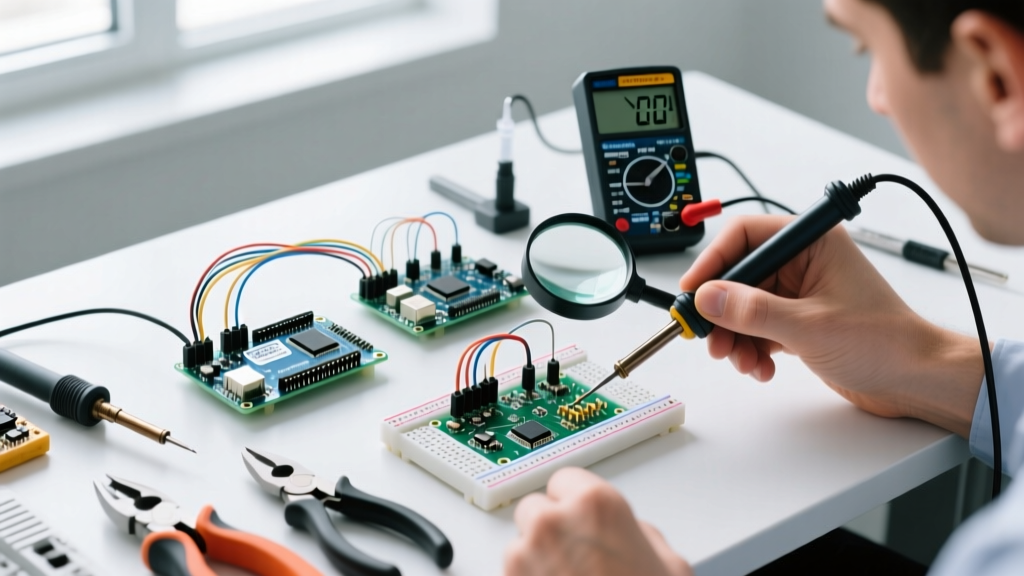
- Non-Destructive Optical Inspection: Use a stereo microscope at 40x-100x magnification. Look for crystalline, fern-like structures bridging the gap. ECM dendrites often appear blue/green (copper) or white/silver (tin/silver).
- Curve Tracing: An ECM short often exhibits non-linear, diode-like I-V characteristics due to the electrochemical nature of the bridge, unlike a fused metallic short from EOS which reads as a dead resistor.
- SEM/EDX Analysis: Scanning Electron Microscopy with Energy Dispersive X-ray Spectroscopy will definitively identify the elemental composition of the dendrite and map the migration path from anode to cathode.
Validating Assembly Reliability with SIR Testing
Before committing a new PCB assembly process to mass production, mandate Surface Insulation Resistance (SIR) testing. As outlined by the Surface Mount Technology Association (SMTA), SIR testing evaluates the electrochemical reliability of the flux and cleaning process. Test coupons are subjected to 85°C and 85% Relative Humidity with a 50V bias for 7 days. To pass, the insulation resistance must remain above 100 MΩ (10^8 Ω) without dropping by more than one order of magnitude, ensuring no latent dendritic growth will occur in the field.
Summary
Metal migration in electronic components is a preventable but unforgiving failure mode. As component pitches shrink and operating voltages in sectors like EV and renewable energy climb, the margin for error in PCB assembly vanishes. By enforcing strict flux control, validating cleanliness via ROSE testing, and applying the correct conformal coating, engineering teams can effectively neutralize the ECM threat and ensure long-term operational safety.