
The 2026 Landscape of Component Identification
As surface-mount device (SMD) footprints shrink to 0201 and 01005 imperial sizes in 2026, visual identification of passive and active components is nearly impossible without professional magnification. Furthermore, electrical identification requires sub-milliohm precision and high-frequency testing to differentiate between ceramic, tantalum, and electrolytic capacitors. Whether you are reverse-engineering a legacy PCB, repairing modern consumer electronics, or sorting through a bin of unmarked salvage parts, having the right toolkit is non-negotiable.
This comprehensive equipment roundup covers the most reliable, accurate, and cost-effective tools for identifying electronic components available on the market today. From high-precision LCR smart tweezers to optical inspection microscopes, we break down the exact models, pricing, and real-world edge cases you need to know.
Equipment Matrix: Top Gear for Identifying Electronic Components
| Tool Category | Top 2026 Model | Best Use Case | Approx. Price | Critical Spec |
|---|---|---|---|---|
| Smart Tweezers | Siborg ST-5S | In-circuit SMD testing | $169.00 | Auto-select up to 100kHz |
| Component Tester | FNIRSI DSO-TC3 | Zener diodes & optocouplers | $65.00 | 30V Zener test capability |
| USB Microscope | Andonstar AD409 Pro | Reading laser SMD codes | $189.00 | Polarized light filter |
| Software Database | Electrodoc Pro | Pinout & SMD code lookup | $4.99 | Offline SMD codebook |
High-Precision LCR Smart Tweezers
Siborg Smart Tweezers ST-5S vs. Peak Atlas LCR45
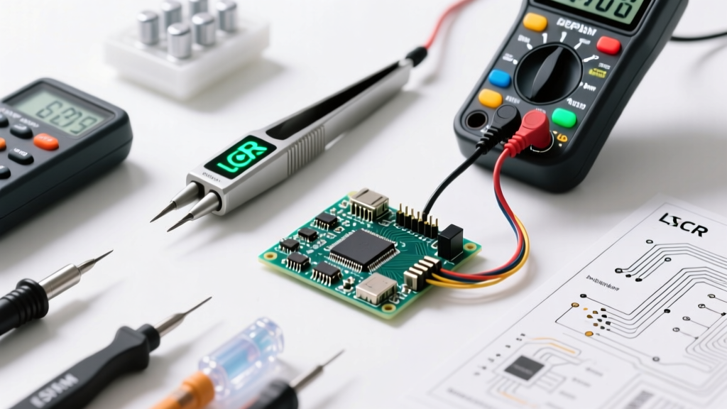
When identifying unmarked SMD capacitors and resistors directly on a populated PCB, standard multimeter probes are too cumbersome and inaccurate due to contact resistance. Smart tweezers solve this by integrating the test probes and the measurement bridge into a single handheld form factor.
The Siborg ST-5S ($169) remains the gold standard for professional repair technicians in 2026. Its primary advantage is its automatic test frequency selection (100Hz, 120Hz, 1kHz, 100kHz). This is critical because ceramic capacitors (Class II dielectrics like X7R) exhibit significant capacitance drop-off at higher frequencies and DC bias voltages. The ST-5S allows you to measure the equivalent series resistance (ESR) at 100kHz, which is the exact frequency used by most switching power supplies, giving you a true picture of the component's health in-circuit.
For hobbyists and field technicians, the Peak Atlas LCR45 ($115) offers a slightly bulkier but highly reliable alternative. While it lacks the integrated tweezer tips (requiring you to attach standard probes), its color-coded LCD and audible pass/fail indicators make it incredibly fast for sorting bins of through-hole and leaded SMD components.
Expert Tip: Always measure capacitors using the 'Parallel' (Cp) equivalent circuit model for high-impedance components (like small ceramic caps under 10nF) and the 'Series' (Cs) model for low-impedance components (like large electrolytics). Using the wrong model on your LCR meter will yield wildly inaccurate readings.
Multi-Function Testers: The FNIRSI DSO-TC3 Deep Dive
Multi-function component testers have flooded the market, but most cheap clones fail when testing specialized semiconductors. The FNIRSI DSO-TC3 ($65) stands out in 2026 because it combines a 3-in-1 architecture: a component tester, a signal generator, and a basic oscilloscope.
Where the DSO-TC3 truly shines in identifying electronic components is its dedicated Zener diode test socket. Unlike older Mega328-based testers that max out at 5V, the DSO-TC3 utilizes an internal boost converter to output up to 30V. This allows you to accurately identify the breakdown voltage of 12V, 15V, and 24V Zener diodes, which are ubiquitous in industrial control boards and power supply feedback loops.
Pros and Cons of the DSO-TC3
- Pro: Built-in 30V Zener testing eliminates the need for a bench power supply and current-limiting resistor setup.
- Pro: Color screen clearly maps out the pinout of complex optocouplers and triacs.
- Con: The ZIF socket is fragile; attempting to force thick TO-220 transistor leads can bend the internal contacts.
- Con: Cannot accurately measure high-frequency inductors due to limited test signal bandwidth.
Optical Identification: USB Microscopes for Laser Codes
Identifying SMD transistors, MOSFETs, and voltage regulators often relies entirely on reading microscopic 2- or 3-character laser codes printed on SOT-23 and SOT-223 packages. In 2026, glossy epoxy finishes and high-density board layouts create immense glare, rendering standard magnifying loupes useless.
The Andonstar AD409 Pro ($189) is specifically engineered for this task. It features a 1080p HDMI output and, most importantly, an adjustable polarized light filter. By rotating the polarizing lens over the LED ring light, you can completely eliminate the specular reflection off glossy black IC packages, revealing faint laser etchings that are otherwise invisible to the naked eye.
For deciphering these obscure markings, Electronics Notes provides an extensive guide on SMD transistor codes that pairs perfectly with optical inspection. Once you read the code (e.g., '1AM'), you can cross-reference it to find the actual part number (MMBT3904 NPN transistor).
Software Databases and SMD Codebooks
Hardware is only half the battle. When identifying electronic components, you need immediate access to pinout diagrams and SMD code databases. Electrodoc Pro (formerly ElectroDroid, $4.99 on mobile platforms) remains the undisputed champion of workbench reference software in 2026. Its offline SMD code database contains over 150,000 entries, covering everything from standard bipolar junction transistors to obscure RF mixers.
Additionally, utilizing manufacturer-specific datasheets is crucial. When a component is partially burned, the physical package outline (e.g., SOIC-8 vs. MSOP-8) combined with the pin 1 indicator dot can help you narrow down the search in Electrodoc before applying power to the circuit.
Troubleshooting Edge Cases in Component ID
Real-world repair rarely involves pristine, perfectly labeled components. Here are specific edge cases you will encounter and how to identify them:
1. The Tantalum Capacitor Polarity Trap
One of the most dangerous misidentifications in electronics involves tantalum capacitors. Unlike aluminum electrolytic capacitors, where the painted stripe indicates the negative cathode, the stripe on a surface-mount tantalum capacitor indicates the positive anode. Reversing the polarity on a tantalum capacitor during replacement will cause catastrophic thermal runaway, resulting in a violent explosion and fire. Always verify the anode/cathode markings on the PCB silkscreen against the physical component before soldering.
2. Identifying Counterfeit and Sanded ICs
The secondary market is flooded with counterfeit operational amplifiers and voltage regulators. Fraudsters often sand down the top of a cheap, low-spec IC and laser-print the markings of a premium, high-spec component (e.g., marking a generic LM358 as a precision OPA2134). To identify these fakes without decapsulating the chip, use your multimeter's diode test mode. Measure the forward voltage drop of the internal ESD protection diodes from every pin to the ground pin. Compare this 'pin signature' matrix against a known genuine datasheet. As outlined in the IPC-7711/7721 standards for electronic assembly rework, verifying component integrity before and after rework is essential for maintaining circuit reliability.
3. Degraded Vintage Epoxy Markings
When repairing vintage audio or industrial equipment from the 1980s, the white silkscreen and epoxy paint used to mark diodes and transistors often flakes off. If the physical marking is gone, desolder the component and use the FNIRSI DSO-TC3 to identify the semiconductor junction type (NPN, PNP, JFET, or MOSFET) and its pinout, then measure the physical dimensions to source a modern equivalent.
Frequently Asked Questions
How do I identify a blown SMD capacitor?
Visually, a failed ceramic capacitor may show a hairline crack or a charred edge, but many fail internally with no visual cues. Electrically, a shorted SMD capacitor will read near 0 ohms on a multimeter. To confirm, you must desolder one end of the capacitor from the PCB pad and measure it again; if it still reads as a dead short, the capacitor has suffered dielectric breakdown and must be replaced.
Can I use a standard multimeter to identify inductors?
No. A standard multimeter can only measure the DC resistance (DCR) of the copper wire inside the inductor, which will usually read between 0.5 and 10 ohms regardless of the inductance value. To accurately identify an inductor's microhenry (µH) or millihenry (mH) rating, you must use an LCR meter capable of applying an AC test signal, such as the Siborg ST-5S.
Where can I find ongoing reviews of budget component testers?
For ongoing community teardowns, firmware hacks, and reviews of budget testers, the Hackaday component tester archives remain an invaluable resource for DIYers and professional technicians looking to push cheap hardware beyond its factory limitations.