
The Hidden Dangers in Active Components Electronics
When designing, assembling, or repairing circuits, understanding the physical vulnerabilities of your parts is just as critical as understanding their schematic symbols. Unlike passive components (resistors, capacitors, inductors) which generally fail only under extreme overvoltage or overcurrent, active components electronics—such as MOSFETs, BJTs, operational amplifiers, and microcontrollers—are highly sensitive to their environment. They require external power to operate and can amplify or switch signals, but this complexity makes them susceptible to invisible threats like electrostatic discharge (ESD), thermal runaway, and parasitic latch-up.
In 2026, as semiconductor geometries continue to shrink into the sub-3nm node for advanced logic and sub-20nm for power ICs, the gate oxides and junction barriers in active components are thinner and more fragile than ever. A handling mistake that would have been harmless a decade ago can now instantly destroy a modern silicon die. This guide outlines the strict safety and best practice protocols required to handle, solder, and store active components electronics without degrading their lifespan or causing latent failures.
ESD Mitigation: Protecting Silicon at the Bench
Electrostatic Discharge (ESD) is the silent killer of active components electronics. According to the ESD Association, the human body can generate static charges exceeding 10,000 volts in low-humidity environments, yet humans cannot feel a discharge until it reaches approximately 3,000 volts. Modern CMOS gate oxides can be punctured by as little as 20 volts.
Latent ESD Damage Warning: Not all ESD events cause immediate catastrophic failure. A 'latent defect' occurs when the gate oxide is partially degraded. The component will pass initial testing but will fail prematurely in the field, often costing thousands of dollars in warranty returns and reputation damage.
Setting Up a Compliant EPA (Electrostatic Protected Area)
To safely handle active components electronics, your workbench must be a properly grounded EPA. Do not rely on 'anti-static' sprays or generic mats. You need a verified, hard-grounded system.
- Worksurface Matting: Use a dissipative rubber mat like the 3M 8214 Dual-Layer Mat (approx. $45 for a 24x36 inch section). The top layer is static-dissipative (10^6 to 10^8 ohms/sq), while the bottom layer is conductive to bleed charges to ground.
- Grounding Cord: Connect the mat to a verified earth ground using a 1-megohm current-limiting resistor cord. This protects the user from shock if they accidentally touch live mains voltage while grounded.
- Wrist Strap: Wear a continuous monitor wrist strap, such as the Desco 19784 (approx. $25). This model features an integrated banana jack and ensures your skin resistance is kept in parallel with the mat, equalizing your potential with the components.
- Ionization: For environments with unavoidable insulators (like plastic component trays or FR4 bare boards), use a benchtop ionizer (e.g., Hakko 490B) to flood the area with balanced positive and negative ions, neutralizing static charges that cannot be drained via a ground wire.
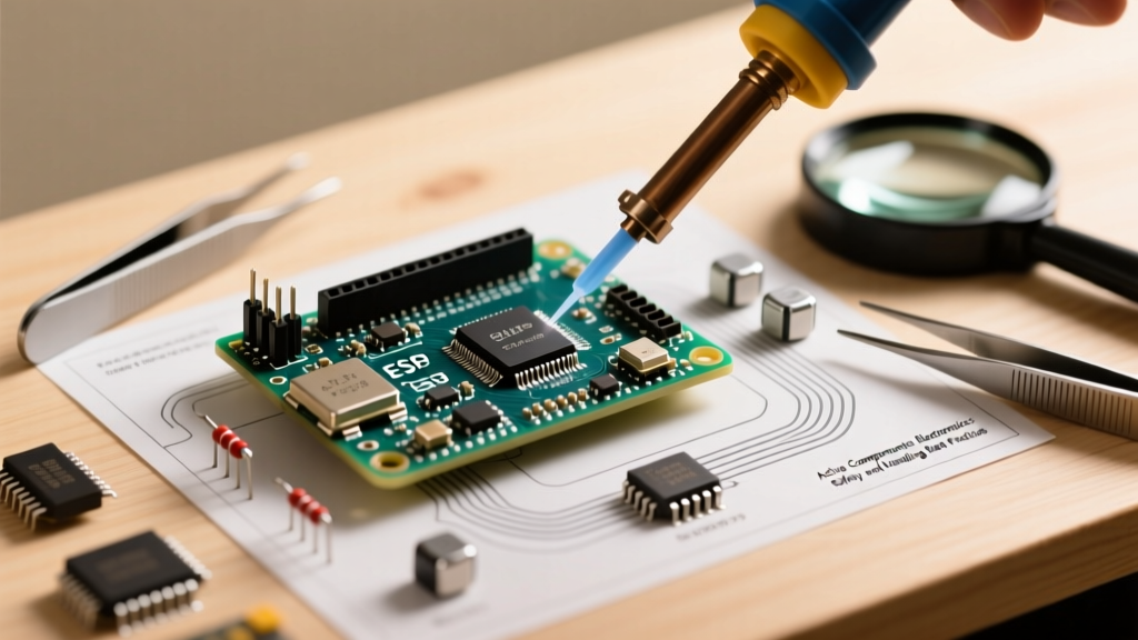
Thermal Management and Soldering Protocols
Active components electronics are highly sensitive to thermal shock and prolonged heat exposure. Excessive heat during soldering can cause die-attach delamination, wire-bond lifting, or package cracking (the 'popcorn effect' in moisture-compromised parts).
Soldering Station Selection and Tip Geometry
For hand-soldering active ICs, avoid cheap stations with slow thermal recovery. Use a station with high wattage and rapid sensor feedback, such as the Hakko FX-951 (approx. $350) or Weller WE1010NA (approx. $110). Crucially, use the largest tip geometry that the pad allows. A chisel tip transfers heat via conduction much faster than a micro-pencil tip, allowing you to use a lower iron temperature and shorter dwell time.
Maximum Temperature and Dwell Time Matrix
The following table outlines the safe hand-soldering limits for common active component packages. Exceeding these limits risks permanent silicon degradation.
| Package Type | Max Iron Temp | Max Dwell Time (Per Pin) | Required Tip Style |
|---|---|---|---|
| DIP / TO-220 (Through-Hole) | 350°C (662°F) | 3 - 5 seconds | Large Chisel / Bevel |
| SOIC / SSOP (SMD) | 320°C (608°F) | 2 - 3 seconds | Medium Chisel / Gull-wing |
| QFN / DFN (Bottom Pads) | 300°C (572°F) | Use Hot Air (350°C) | Hot Air Nozzle / Preheater |
| BGA (Ball Grid Array) | N/A (No Iron) | Profile-dependent | BGA Rework Station Only |
Preventing Thermal Runaway in Power Transistors
When designing with active components electronics that handle high current, you must account for thermal runaway. Bipolar Junction Transistors (BJTs) have a negative temperature coefficient for their base-emitter voltage (Vbe). As the transistor heats up, Vbe drops, causing it to draw more base current, which generates more heat, leading to a destructive feedback loop.
Best Practice: Always include an emitter degeneration resistor (typically 0.1Ω to 1Ω) in BJT power stages to provide negative feedback and stabilize the bias current. Conversely, modern Power MOSFETs have a positive temperature coefficient for their on-resistance (Rds(on)), making them inherently more stable when paralleled, but they still require adequate heatsinking and thermal interface material (TIM) like Arctic Silver 5 or high-performance phase-change pads like Honeywell PTM7950.
Latch-Up and Overvoltage Protection Strategies
Latch-up is a catastrophic failure mode specific to CMOS active components electronics. It occurs when a parasitic PNPN thyristor structure (inherent in the CMOS manufacturing process) is accidentally triggered by a voltage spike or a fast transient on an I/O pin. Once triggered, it creates a low-impedance short between VCC and Ground, drawing massive current until the device melts or the power is removed.
Clamping and TVS Diode Implementation
To prevent latch-up and protect sensitive inputs from inductive kickback or external ESD strikes, you must clamp transient voltages before they reach the IC's internal protection diodes. According to Texas Instruments ESD Protection guidelines, external Transient Voltage Suppression (TVS) diodes are mandatory for any active component connected to external cables or long traces.
- Low-Capacitance Data Lines: Use the Littelfuse SP0503BAHTG or Nexperia PESD5V0S1BA. These offer clamping voltages under 10V and capacitance below 1pF, ensuring they do not distort high-speed USB or Ethernet signals.
- Power Rails: Use unidirectional TVS diodes (e.g., SMAJ5.0A) placed as physically close to the active component's power entry pin as possible.
- Current Limiting: Always place a small series ferrite bead or a 10Ω to 50Ω resistor on I/O lines to limit the peak surge current that the TVS diode must shunt to ground.
Storage and Moisture Sensitivity Levels (MSL)
Active components electronics packaged in organic plastics (like epoxy-molded QFNs and BGAs) are hygroscopic—they absorb moisture from the ambient air. When exposed to the high temperatures of a reflow oven (up to 260°C for lead-free RoHS compliance), the trapped moisture turns to steam, expanding rapidly and cracking the package from the inside out.
The JEDEC J-STD-020 Standard classifies components by their Moisture Sensitivity Level (MSL). Understanding these levels is non-negotiable for safe assembly.
MSL Ratings and Bench Life
- MSL 1: Unlimited floor life. Not sensitive to moisture. (e.g., standard through-hole DIP ICs).
- MSL 2: 1-year floor life at <30°C / 60% RH.
- MSL 3: 168 hours (1 week) floor life. Highly common for modern SMD microcontrollers and FPGAs.
- MSL 4 to 6: 72 hours down to 24 hours. Requires immediate soldering or dry-box storage.
Recovery and Baking Protocols
If an MSL 3 or higher active component exceeds its floor life, it must not be soldered. It must be baked in a convection oven at 125°C for 24 hours to drive out the moisture. Warning: Do not bake components in embossed plastic tape-and-reel packaging that is not rated for 125°C, as the carrier tape will melt and warp. Transfer them to high-temperature metal trays before baking.
Frequently Asked Questions (FAQ)
Can I use a standard multimeter to test for ESD damage on an active component?
No. Standard multimeters lack the sensitivity to detect micro-fractures in gate oxides or latent ESD damage. You would need a semiconductor curve tracer to compare the I-V characteristics of the suspect pin against a known-good golden sample. In a DIY or standard repair shop, if you suspect ESD damage on a microcontroller or op-amp, the safest practice is to replace the IC entirely.
Is it safe to store active components electronics in standard plastic zip-lock bags?
Absolutely not. Standard polyethylene zip-lock bags are highly triboelectric and will generate massive static charges when rubbed against the components. Always store active parts in their original Moisture Barrier Bags (MBB) with desiccant and humidity indicator cards, or use specialized pink anti-poly bags (for short-term physical protection only) or metalized static-shielding bags for long-term storage.