
Understanding the Electronic Switch Component Landscape
When prototyping a custom PCB or wiring a breadboard, selecting the right electronic switch component dictates your circuit's efficiency, thermal profile, and overall lifespan. Unlike mechanical relays that suffer from contact bounce, arcing, and physical wear, solid-state electronic switches offer microsecond switching times, silent operation, and virtually infinite cycle life. However, they introduce new complexities regarding thermal management, gate drive requirements, and isolation.
Before diving into specific circuit applications, it is critical to understand the trade-offs between the four primary switching technologies used in modern DIY electronics and prototyping.
| Technology | Standard Model | Max Continuous Current | Control Signal | Switching Speed | Approx. Cost (2026) |
|---|---|---|---|---|---|
| Bipolar Junction Transistor (BJT) | 2N2222 | 800 mA | Current-driven (Base) | Fast (~100 ns) | $0.10 - $0.15 |
| N-Channel Logic-Level MOSFET | IRLZ44N | 47 A | Voltage-driven (Gate) | Very Fast (~50 ns) | $1.20 - $1.80 |
| Solid-State Relay (SSR) | Omron G3MB-202P | 2 A (AC) | Opto-isolated LED | Zero-cross dependent | $3.50 - $4.50 |
| Electromechanical Relay | SRD-05VDC-SL-C | 10 A | Current-driven (Coil) | Slow (~5-10 ms) | $1.50 - $2.00 |
Tutorial 1: Driving High-Current DC Loads with a Logic-Level MOSFET
For switching high-current DC loads like 12V LED strips, DC motors, or heating elements from a 3.3V or 5V microcontroller (like an ESP32 or Arduino), the N-channel logic-level MOSFET is the undisputed champion. A common beginner mistake is using the IRF520 module; while cheap, the IRF520 requires a 10V gate drive to fully turn on, leading to massive heat dissipation when driven by a 5V GPIO pin. Instead, we use the IRLZ44N, which is fully enhanced at a $V_{GS}$ of 5V.
Step-by-Step Wiring and Component Selection
- The Gate Resistor (220Ω): Never connect a microcontroller GPIO directly to a MOSFET gate. The gate acts like a small capacitor (input capacitance for the IRLZ44N is ~2200 pF). When the GPIO goes HIGH, it briefly looks like a short circuit, drawing high inrush current that can damage the MCU. Place a 220Ω resistor in series to limit this charging current.
- The Pull-Down Resistor (10kΩ): Wire a 10kΩ resistor between the Gate and Source (GND). If your microcontroller resets or its GPIO pins float during boot, this resistor ensures the MOSFET remains firmly in the OFF state, preventing your load from turning on unexpectedly.
- The Flyback Diode (1N4007 or Schottky): If your load is inductive (a motor, solenoid, or relay coil), you must place a flyback diode in reverse parallel across the load. When the MOSFET turns off, the collapsing magnetic field generates a massive reverse voltage spike that will instantly punch through the MOSFET's drain-source junction.
Thermal Calculation and Edge Cases
Let's calculate the heat dissipation for an IRLZ44N switching a 10A load at 5V gate drive. According to the datasheet, the $R_{DS(on)}$ (on-state resistance) is approximately 22 mΩ (0.022Ω) at $V_{GS} = 5V$.
Power Dissipation Formula: $P = I^2 \times R_{DS(on)}$
$P = 10^2 \times 0.022 = 100 \times 0.022 = 2.2$ Watts.
A standard TO-220 package without a heatsink has a thermal resistance of about 62°C/W to ambient. Dissipating 2.2W will raise the junction temperature by roughly 136°C above ambient, which will trigger thermal shutdown or destroy the silicon. You must attach a small extruded aluminum heatsink (e.g., 15°C/W) to keep the component within safe operating limits. For currents above 15A, consider paralleling two MOSFETs or moving to a D2PAK surface-mount component soldered to a large copper pour.
For deeper insights into gate charge dynamics and switching losses, refer to the Texas Instruments application note on Power MOSFET basics, which details how Miller capacitance affects switching times.
Tutorial 2: Isolating AC Mains with a Solid-State Relay (SSR)
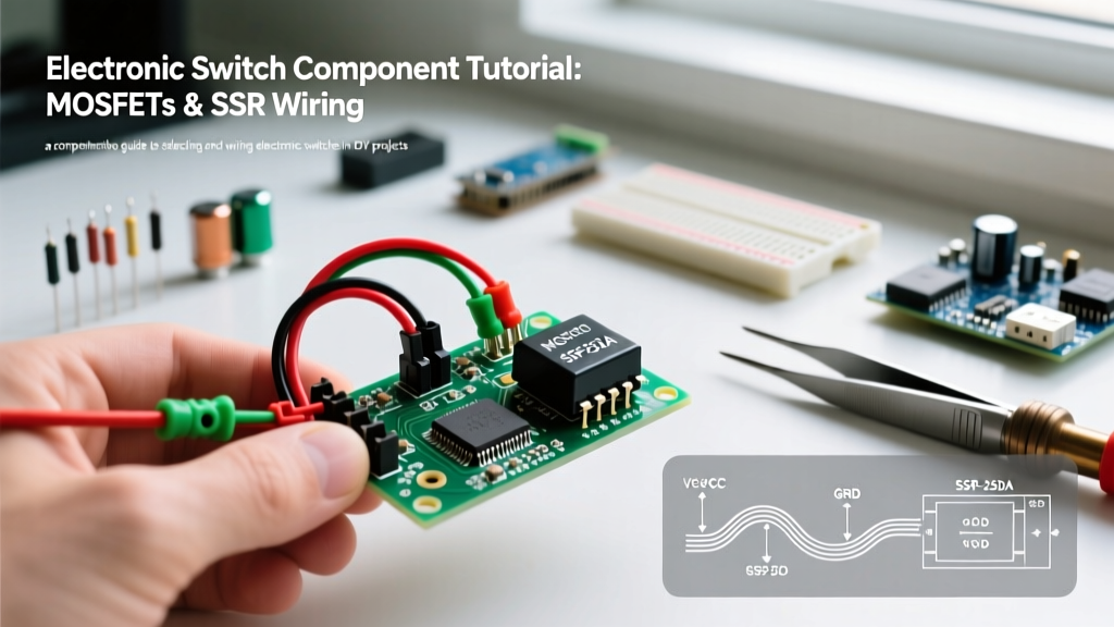
When your application requires switching 120V/240V AC mains—such as controlling an AC water heater, an espresso machine, or stage lighting—you must prioritize galvanic isolation. The Omron G3MB-202P is a highly reliable, compact electronic switch component designed specifically for this. It switches up to 2A at 240VAC and provides optical isolation between the low-voltage DC control side and the high-voltage AC load side.
Wiring the SSR for AC Loads
- Input Side (DC Control): The G3MB-202P contains an internal LED. Connect the 'DC-' terminal to your circuit ground. Connect the 'DC+' terminal to your microcontroller's 5V GPIO pin through a 330Ω current-limiting resistor. This limits the internal LED current to roughly 10mA, which is sufficient to trigger the internal TRIAC while protecting your MCU.
- Output Side (AC Load): Wire the AC 'Line' (hot) to one of the SSR output terminals. Wire the other SSR output terminal to one side of your AC load. Connect the other side of the AC load to the AC 'Neutral'. Never switch the neutral line; always switch the hot line for safety.
Zero-Crossing vs. Random Phase Switching
The G3MB-202P is a zero-crossing SSR. This means that when you send a HIGH signal to the input, the internal TRIAC will not actually turn on until the AC sine wave crosses the 0V threshold. This drastically reduces Electromagnetic Interference (EMI) and inrush currents, making it perfect for resistive loads like heating elements and incandescent bulbs.
However, zero-crossing SSRs are poor choices for highly inductive AC loads like large AC motors or transformers. The phase shift between voltage and current in inductive loads can cause the TRIAC to fail to commutate (turn off) when the control signal is removed, resulting in the load running continuously. For inductive AC loads, you must select a 'random phase' SSR or stick to an electromechanical contactor. For comprehensive safety and mounting guidelines, consult the Omron Solid State Relay product documentation.
Critical Failure Modes in Prototyping
Even with the correct electronic switch component, prototyping environments are prone to specific failure modes that do not appear in simulation software like LTspice.
1. Gate Float and Miller Effect
During the breadboarding phase, long jumper wires act as antennas. High $dv/dt$ (rapid voltage changes) on the drain side of a MOSFET can couple through the Miller capacitance ($C_{gd}$) back to the gate, causing the MOSFET to spontaneously turn on and oscillate. Always keep gate drive traces as short as possible on your final PCB, and never leave a gate un-pulled-down during testing.
2. Thermal Runaway in Paralleled BJTs
If you need more current than a single BJT (like the TIP31C) can handle, do not simply wire two BJTs in parallel. BJTs have a negative temperature coefficient; as one gets hotter, its $V_{BE}$ drops, causing it to draw more current, get even hotter, and eventually fail in a cascading thermal runaway. MOSFETs, conversely, have a positive temperature coefficient ($R_{DS(on)}$ increases with heat), which naturally balances the current between paralleled devices.
Summary Checklist for Component Selection
Before finalizing your schematic, run through this decision matrix:
- Is the load DC and under 800mA? Use a BJT (2N2222) or a small logic-level MOSFET (2N7000).
- Is the load DC and over 1A? Use a logic-level N-Channel MOSFET (IRLZ44N) with appropriate gate resistors and heatsinking.
- Is the load AC mains (resistive)? Use a zero-crossing SSR (Omron G3MB-202P) with optical isolation.
- Is the load AC mains (inductive) or >10A? Use an electromechanical relay or a heavy-duty contactor driven by a smaller electronic switch.
By matching the specific electrical characteristics of your load to the correct electronic switch component, you ensure a robust, thermally stable, and safe circuit design that will transition smoothly from the breadboard to a finalized printed circuit board.