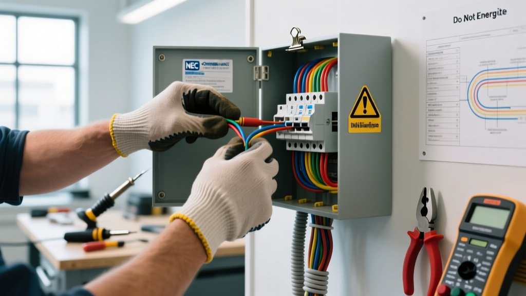

Metal-Clad (MC) cable is the backbone of commercial, industrial, and multi-family residential electrical systems. Recognized for its crush resistance, fire-rated assembly capabilities, and built-in equipment grounding conductor (EGC), MC cable is a massive upgrade over standard NM-B (Romex). However, when a fault occurs within an MC cable run, troubleshooting is significantly more complex. The corrugated aluminum or steel armor hides the internal conductors, and the sheer length of commercial runs makes pinpointing a hidden short or ground fault a formidable challenge.
Unlike simple residential wiring, troubleshooting MC cables requires an understanding of armored termination mechanics, specialized testing equipment, and strict adherence to the National Electrical Code (NEC). This guide dives deep into the most common failure modes of MC cables and provides actionable, expert-level frameworks for isolating and resolving them.
Diagnostic Toolkit for Metal Clad Cable Systems
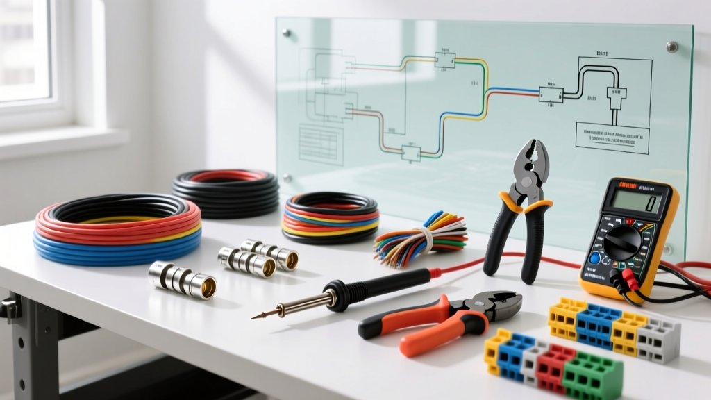
Standard multimeters are insufficient for diagnosing insulation breakdowns or high-resistance ground faults in long MC cable runs. To properly troubleshoot metal-clad systems, electrical professionals must deploy advanced diagnostic instruments:
- Insulation Multimeter (e.g., Fluke 1587 FC): Combines a digital multimeter with an insulation resistance tester (Megohmmeter). Essential for applying 500V or 1000V DC to stress-test the THHN/THWN-2 insulation inside the armor without damaging it.
- Time Domain Reflectometer (TDR): Devices like the Megger TDR330 send a low-energy pulse down the cable. By measuring the time it takes for the reflection to return, a TDR can pinpoint the exact distance to a break, short, or water ingress point in runs exceeding 1,000 feet.
- Micro-ohmmeter: Used specifically to test the continuity and resistance of the MC cable’s metal armor when it is being utilized as the primary Equipment Grounding Conductor.
Termination and Anti-Short Bushing Faults
The single most common cause of ground faults in MC cable systems occurs at the termination point inside junction boxes or panelboards. When MC cable is cut, the corrugated metal armor leaves a razor-sharp inward-facing burr. If this burr is not managed, it will slice directly into the insulation of the internal conductors when the cable is pushed into the metal box.
The "Red Head" Bushing Failure Mode
NEC Article 330 requires the use of an anti-short bushing (colloquially known as a "red head" due to its standard color) to protect the conductors from the sharp armor edge. A frequent troubleshooting scenario involves a breaker that trips intermittently, especially when a wall is bumped or a heavy door slams nearby. This is almost always caused by a missing or improperly seated anti-short bushing. The vibration causes the sharp armor edge to momentarily pierce the THHN insulation and arc against the grounded metal box.
The Fix: Pull the MC cable out of the box. Inspect the THHN insulation for circular scoring or carbon tracking. If the insulation is compromised, the cable must be cut back, re-stripped using a specialized MC cable rotoskin tool, and re-terminated with a new, properly seated anti-short bushing and an approved set-screw or compression fitting (such as the Arlington MC900 series).
Grounding Path Continuity: Armor vs. Internal Wire
Modern MC cable typically contains an internal green insulated equipment grounding conductor. However, under specific conditions, the metal armor itself is also permitted to serve as an EGC. Troubleshooting grounding issues requires understanding the difference between the two paths.
According to the NFPA National Electrical Code Section 250.118(10), Type MC cable armor can serve as an equipment grounding conductor if it is listed and identified as such, and if the combined grounding path of the armor and any internal grounding wire meets the low-impedance requirements of 250.4.
Troubleshooting Ground Loop and Noise Issues: In sensitive environments like hospitals or data centers, relying solely on the corrugated armor for grounding can introduce electromagnetic interference (EMI) or create high-impedance ground loops due to oxidation at the fitting connections. If you are troubleshooting sensitive equipment resets or data packet loss, test the micro-ohm resistance between the panel ground bar and the equipment chassis. If the resistance exceeds 0.1 ohms, the armor connections are likely oxidized or loose. You must verify that the internal green EGC is securely landed on both ends and that the MC fittings are torqued to the manufacturer’s exact specifications to ensure a parallel, low-impedance ground path.
Identifying Physical Armor and Jacket Breaches
While MC cable is rugged, it is not invincible. Physical damage to the armor alters the cable’s electrical characteristics and compromises its safety rating.
Bend Radius Violations
NEC 330.24 strictly dictates the minimum bending radius for MC cable. For standard MC cable, the inner edge of the bend cannot be less than seven times the cable diameter. When installers force MC cable into tight 90-degree bends using improper hand-bending techniques, the corrugated armor can kink. A kink compresses the internal paper or polymer separator, crushing the THHN insulation against the internal EGC or adjacent phase conductors, resulting in a dead short that may not trip until the circuit is fully loaded and the conductors expand from heat.
Moisture Ingress in Standard MC
Standard MC cable is not rated for wet locations. If installed in an area subject to condensation or minor water exposure, moisture wicks into the paper binders inside the armor. This drastically lowers the insulation resistance. If you are troubleshooting unexplained GFCI trips on a 20A commercial circuit, perform an insulation resistance test. Readings below 1 megohm on a 500V DC test strongly indicate moisture ingress, requiring the replacement of the run with MC-HL (Hazardous Location) or MC cable featuring a continuous PVC jacket over the armor.
Advanced Fault Location: TDR and Megger Testing
When a fault is confirmed but the physical location is hidden behind drywall or above hard-lid ceilings, guessing is not an option. Below is a comparison of the two primary advanced testing methods used by commercial electricians to isolate MC cable faults.
| Testing Method | Primary Use Case | How It Works | Limitations |
|---|---|---|---|
| Megohmmeter (Megger) | Insulation breakdown, moisture ingress, and phase-to-ground leakage. | Applies high DC voltage (500V-1000V) to stress the insulation and measure leakage current in megohms. | Cannot tell you *where* the fault is located; only confirms its existence and severity. |
| Time Domain Reflectometry (TDR) | Locating exact distance to open circuits, dead shorts, or crushed armor. | Sends a low-voltage pulse down the conductor and measures the nanosecond reflection time from impedance changes. | Less effective for high-resistance ground faults; requires knowing the exact velocity factor of the cable. |
For comprehensive troubleshooting, best practice dictates using a Megohmmeter to confirm the presence of an insulation fault, followed by a TDR to measure the exact footage to the fault from the panel. For more on the principles of insulation testing, refer to this Fluke guide on insulation resistance testing.
Step-by-Step Isolation Protocol for Intermittent Shorts
Intermittent shorts in MC cable are notoriously difficult to track down because standard continuity testers only apply a few volts, which is not enough to bridge a microscopic gap caused by a crushed internal separator. Follow this 5-step isolation protocol:
- De-energize and Isolate: Lock out the breaker and disconnect both the line and load ends of the suspected MC run. Remove all pigtails and wire nuts.
- Perform a Baseline Megger Test: Test Phase-to-Ground, Phase-to-Neutral, and Neutral-to-Ground at 500V DC. Note the baseline megohm readings. (Note: Ensure all sensitive electronics and surge suppressors are disconnected, as 500V will destroy solid-state components).
- Flex the Terminations: While the Megger is actively testing (or using a continuous continuity alarm), physically manipulate the MC cable at every junction box, ceiling grid, and panel entry. If the alarm triggers when bending a specific fitting, the anti-short bushing has failed or the armor is pinching a wire.
- Divide and Conquer: If the fault is confirmed but the location is unknown, find the midpoint of the run (usually a junction box or a device daisy-chain). Open the midpoint, separate the cables, and Megger both halves. This halves your search area instantly.
- Inspect for Strut Crush Damage: In commercial spaces, MC cable is often strapped to Unistrut. Inspect all strut clamps. Over-tightened beam clamps can deform the aluminum armor enough to press the internal EGC into the hot conductor. Replace crushed sections or loosen and re-seat the clamps using proper MC cable ties that distribute pressure evenly.
Final Thoughts on MC Cable Integrity
Troubleshooting MC cables requires a shift in mindset from residential wiring. You are not just testing copper conductors; you are evaluating a complex, multi-layered mechanical and electrical assembly. By utilizing high-voltage insulation testing, respecting the mechanical limits of the corrugated armor, and ensuring flawless terminations with anti-short bushings, you can quickly isolate faults and restore the immense reliability that metal-clad wiring is known for. Always consult the latest OSHA and NEC wiring method standards to ensure your troubleshooting repairs remain fully code-compliant.