
The "DTH11" vs DHT11: Clarifying the Sensor Identity
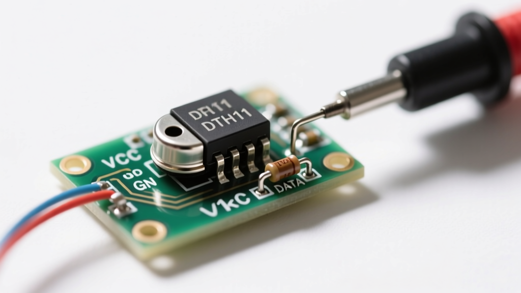
If you have been searching for a dth11 humidity sensor, you are not alone. "DTH11" is one of the most common typographical errors in the DIY electronics and microcontroller community. The correct technical designation for this ubiquitous, low-cost temperature and humidity component is the DHT11. Manufactured originally by Aosong Electronics, this sensor utilizes a single-bus digital protocol to communicate with microcontrollers like the Arduino Uno, ESP8266, and ESP32.
Despite its popularity in beginner kits, the DHT11 is notorious for throwing frustrating errors: NaN (Not a Number) outputs, timeout failures, or readings stubbornly stuck at 0% relative humidity (RH). Because the sensor relies on strict microsecond-level timing rather than standard hardware protocols like I2C or SPI, troubleshooting requires a deep understanding of its underlying communication architecture. This guide bypasses generic advice and dives straight into advanced, symptom-based diagnostics to get your sensor online.
Symptom 1: Serial Monitor Outputs "NaN" or "Timeout"
The NaN error is the most frequent issue encountered when using the popular Adafruit DHT library or the generic DHT.h library. This error indicates that the microcontroller initiated the read sequence, but the sensor failed to respond within the expected microsecond window.
Root Cause Analysis: The Missing Pull-Up Resistor
The DHT11 single-bus protocol requires the data line to be pulled HIGH when idle. If you are using a bare 4-pin DHT11 component (the blue plastic grid without a PCB), it lacks an internal pull-up resistor. Without it, the data line floats, resulting in garbage data or total timeouts.
- The Fix: Solder a 4.7kΩ resistor between the VCC (Pin 1) and DATA (Pin 2) pins. If you are using a 3-pin PCB module, this resistor is already populated on the board (usually labeled R1). Verify its presence with a multimeter set to resistance mode; probing VCC and OUT should yield approximately 4.7kΩ.
Root Cause Analysis: Violating the 1Hz Sampling Limit
The DHT11 has a relatively slow internal ADC and processing cycle. According to the Adafruit DHT Sensor Library Guide, the sensor requires a minimum of 1 second between read cycles. If your loop() function polls the sensor every 200ms, the sensor will lock up or return NaN.
Pro Tip: Implement a non-blocking timer using
millis()to ensure you only request data every 2,000 milliseconds. Never usedelay(1000)in production firmware, as it halts your microcontroller's ability to handle background tasks like WiFi reconnection.
Symptom 2: Readings Stuck at 0% RH and 0°C
When your serial monitor confidently prints Humidity: 0.00% | Temp: 0.00°C without throwing a timeout error, the microcontroller is successfully receiving a 40-bit data packet, but the payload is entirely zeros. This is rarely a software bug; it is almost always a hardware power delivery or counterfeit component issue.
The Power Delivery Droop
The DHT11 draws a momentary spike of current (up to 2.5mA) during the measurement phase. If your breadboard has poor contact resistance or your microcontroller's 3.3V/5V rail is sagging, the sensor's internal microcontroller browns out and resets mid-transmission, sending zeros.
- The Fix: Place a 100nF (0.1µF) ceramic decoupling capacitor as close to the sensor's VCC and GND pins as physically possible. This provides a localized energy reservoir to handle the transient current spike.
- Wire Length Warning: The single-bus protocol degrades rapidly over long distances. Keep the data wire under 20 meters. For runs longer than 2 meters, drop the pull-up resistor value to 2.2kΩ to strengthen the signal rise time.
The Counterfeit Chip Epidemic
Because the DHT11 is so widely used, the market is flooded with cheap clone sensors that use uncalibrated or defective internal thermistors and polymer humidity capacitors. If you have verified your wiring, added decoupling capacitors, and still see 0% RH, you likely have a bad batch. Source your sensors from reputable distributors like Mouser, DigiKey, or verified Adafruit/SparkFun partners rather than ultra-cheap bulk marketplaces.
Symptom 3: Checksum Validation Failures
The DHT11 transmits a 40-bit data frame structured as follows:
- 8-bit Relative Humidity Integer
- 8-bit Relative Humidity Decimal (Always 0 on DHT11)
- 8-bit Temperature Integer
- 8-bit Temperature Decimal (Always 0 on DHT11)
- 8-bit Checksum (Sum of the first four bytes, truncated to 8 bits)
If the sum of the first four bytes does not match the fifth byte, the library throws a Checksum Error and discards the data. This happens when microsecond timing is interrupted.
Microcontroller Interrupts Ruining the Timing
The DHT11 protocol requires the microcontroller to measure HIGH and LOW pulses that are only 20 to 70 microseconds long. If you are using an ESP8266 or ESP32, the underlying RTOS (Real-Time Operating System) constantly fires hardware interrupts to manage WiFi and Bluetooth stacks. If a WiFi interrupt fires exactly when the microcontroller is reading a 50µs pulse from the DHT11, the timing is stretched, the bit is misread, and the checksum fails.
The Fix: Temporarily disable interrupts during the exact millisecond the sensor is being polled. As noted in the Arduino Official Reference, you can wrap your read function like this:
noInterrupts();
float h = dht.readHumidity();
float t = dht.readTemperature();
interrupts();
Note: Disabling interrupts for too long can drop WiFi packets. Ensure your DHT library is optimized to release the interrupt lock as quickly as possible.
Wiring Reference: Bare Component vs. PCB Module
Confusion between the bare 4-pin DHT11 and the soldered 3-pin module leads to countless miswiring errors. Use this table to verify your connections against the Random Nerd Tutorials DHT Guide.
| Pin Function | Bare DHT11 (4-Pin) | PCB Module (3-Pin) | Microcontroller Connection |
|---|---|---|---|
| Power | Pin 1 (VDD) | VCC / + | 3.3V or 5V (Check module specs) |
| Data I/O | Pin 2 (DATA) | OUT / S / DAT | Any Digital GPIO (Add 4.7kΩ pull-up if bare) |
| No Connection | Pin 3 (NC) | Not Present | Leave floating / Do not connect |
| Ground | Pin 4 (GND) | GND / - | System Ground |
Advanced Diagnostic Checklist with a Multimeter
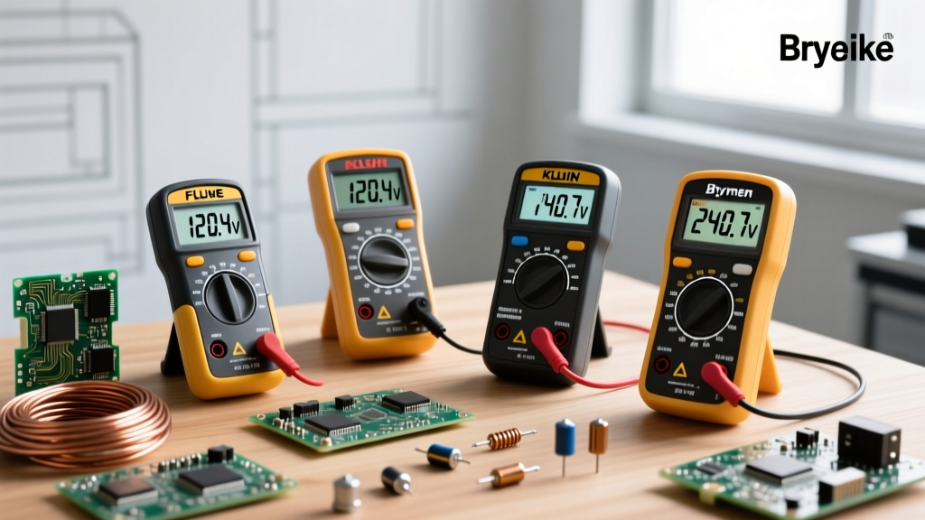
Before throwing away a sensor that refuses to work, put down the code editor and pick up your multimeter. Follow this hardware-level diagnostic sequence:
- Step 1: Verify VCC at the Pins. Set your multimeter to DC Voltage. Probe the VCC and GND pins directly on the sensor housing. You should read a stable 4.8V to 5.1V (or 3.3V depending on your logic level). If it reads below 4.5V on a 5V system, your breadboard rails are suffering from voltage drop.
- Step 2: Check the Pull-Up Continuity. Power down the circuit. Set the multimeter to Resistance (Ω). Probe the VCC and DATA pins. A bare sensor with an external resistor should read ~4.7kΩ. A module should read ~4.7kΩ. If it reads
OL(Over Limit), your pull-up resistor is missing or the solder joint is cold. - Step 3: Rule out Data Line Shorts. Still in Resistance mode, probe the DATA pin and GND pin. It should read
OL. If it reads near 0Ω, your data wire is shorted to ground somewhere on your breadboard, preventing the sensor from pulling the line HIGH.
When to Upgrade: Moving Past the DHT11
The DHT11 is a fantastic learning tool, but it has hard physical limitations: a slow 1Hz sampling rate, a narrow 20-80% RH accuracy range, and a clunky single-bus protocol. If you have exhausted this troubleshooting guide and still require higher reliability for a production environment or a smart home integration, it is time to upgrade.
Consider migrating to the DHT22 (AM2302) for better accuracy and a wider temperature range, or leapfrog entirely to an I2C-based sensor like the BME280 or SHT31. I2C sensors utilize dedicated hardware clock and data lines, completely eliminating the microsecond timing vulnerabilities and interrupt conflicts that plague the DHT11 family.