
The Critical Role of Standardized Schematic Symbols
When engineers and hobbyists discuss the circuit symbols of electronic components, they are rarely just talking about textbook diagrams. In modern 2026 electronics design, a schematic symbol is a complex data object. It must map flawlessly to a physical PCB footprint, integrate with real-time supply chain APIs, and comply with rigorous international standards like IEEE 315 and IEC 60617. A mismatched or poorly managed symbol library can lead to catastrophic board spins, costing thousands of dollars in delayed manufacturing.
As a senior reviewer for ElectricalFlux, I have tested dozens of Electronic Computer-Aided Design (ECAD) platforms and physical reference tools. Below is my comprehensive review of the best tools for creating, managing, and deploying circuit symbols of electronic components, ranging from enterprise-grade suites to open-source powerhouses.
Top ECAD Software for Symbol Management
1. Altium Designer 25: The Enterprise Standard
For professional engineering teams, Altium Designer 25 remains the undisputed heavyweight champion. Its approach to the circuit symbols of electronic components is deeply integrated with its cloud-based Altium 365 workspace.
- Symbol-to-Supply Chain Mapping: Altium's 'Supplier Search' panel allows you to link a schematic symbol directly to real-time Octopart data. If a specific microcontroller's symbol is placed on the schematic, the software instantly verifies stock levels and lifecycle status (e.g., Active vs. NRND).
- IPC Compliance: The built-in library tools enforce IPC-7351 standards, ensuring that the graphical symbol you draw perfectly aligns with the recommended land pattern.
- Pricing: At approximately $325 per month (or $10,000+ for a perpetual enterprise license), it is a significant investment, but the ROI in prevented errors is undeniable for high-layer-count boards.
2. KiCad 8.x / 9.x: The Open-Source Powerhouse
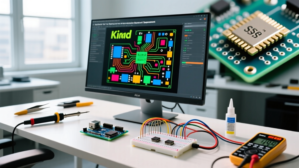
KiCad has evolved from a scrappy underdog to a formidable ECAD suite. The management of circuit symbols of electronic components in KiCad is governed by the strict KiCad Library Convention (KLC).
- Symbol Editor Precision: KiCad's Symbol Editor uses a 50-mil grid by default, perfectly matching the legacy IEEE 315 drafting standards. This ensures that when you draw a custom MOSFET symbol, it will snap cleanly to standard wires without creating invisible 'airwires' (unconnected nets).
- Community Libraries: The official KiCad libraries contain over 40,000 verified symbols. However, the true power lies in creating custom global libraries synced via Git.
- Pricing: 100% Free and open-source. The only cost is the time invested in learning the KLC guidelines.
3. EasyEDA Pro: The Cloud-Native Prototyper
For rapid prototyping and hobbyists, EasyEDA Pro offers a frictionless experience. Its biggest advantage regarding circuit symbols of electronic components is its native integration with the LCSC parts catalog.
- One-Click Symbol Generation: When you select a component from the LCSC library, EasyEDA automatically generates the schematic symbol, the PCB footprint, and even the 3D STEP model. This eliminates 90% of the manual library creation work.
- Limitations: The auto-generated symbols sometimes lack the aesthetic polish or strict IEEE compliance required for formal military or aerospace documentation. You will often need to manually edit the pin placements for complex FPGAs.
- Pricing: Free for standard use; Pro tier is roughly $9.90/month for advanced team collaboration and private cloud libraries.
Feature Comparison Matrix
| Feature | Altium Designer 25 | KiCad (Latest) | EasyEDA Pro |
|---|---|---|---|
| Library Standard | IPC-7351 / Enterprise Custom | KLC v2.0 / IEEE 315 | LCSC Native / User Defined |
| Supply Chain Sync | Native (Octopart / Altium 365) | Via 3rd Party Plugins (e.g., Kitspace) | Native (LCSC Integration) |
| Multi-Unit IC Support | Advanced (Exchangeable Pin Swapping) | Standard (Multi-part symbol mapping) | Basic (Manual grouping required) |
| Estimated Cost | ~$325 / month | Free (Open Source) | Free / $9.90 / month |
Physical Reference Tools for the Workbench
While digital tools dominate PCB layout, physical reference materials remain vital for system architects, patent drafters, and educators who need to sketch circuit symbols of electronic components on whiteboards or paper.
Expert Recommendation: The Encyclopedia of Electronic Components (Volumes 1-3) by Charles Platt (O'Reilly Media) remains the gold standard physical reference. Unlike software libraries that just show a box with pins, Platt's books detail the internal functional block diagrams, pinout variations, and the historical evolution of symbols for everything from SCRs to optocouplers.
For physical drafting, the Rotring Isograph Technical Pen paired with an IEEE 315 Compliant Drafting Stencil (such as those historically produced by Rapidi or Berol) is still utilized by patent attorneys who must submit black-and-white, high-contrast schematic diagrams to the USPTO. A high-quality stencil costs around $15-$25 and ensures that diode triangles and transistor circles maintain exact proportional ratios.
Advanced Troubleshooting: Symbol Edge Cases
Creating the circuit symbols of electronic components is rarely as simple as drawing a rectangle. As a domain expert, I frequently see designers fall into specific traps that pass Design Rule Checks (DRC) but fail in simulation or manufacturing.
1. The Multi-Unit IC Trap (e.g., 74HC00)
When using a Texas Instruments SN74HC00N (a quad 2-input NAND gate), the physical chip is a single 14-pin DIP package. However, the schematic symbol must be split into four separate logical units (A, B, C, D) plus a hidden power unit. The Fix: In KiCad or Altium, ensure that the 'Power' unit (Unit E) explicitly maps Pin 14 to VCC and Pin 7 to GND. If you forget to place this hidden power unit on the schematic, the PCB layout tool will route the logic gates, but the chip will have no physical power traces connected to its pads.
2. Hidden Pins and SPICE Failures
Legacy schematic symbols often hide power and ground pins to reduce visual clutter. While this looks clean, it is a nightmare for SPICE simulations. If a hidden VCC pin defaults to '0V' or 'Unconnected' in the simulation profile, your transient analysis will fail or yield nonsensical floating-node errors. The Fix: Always toggle 'Show Hidden Pins' in your symbol editor before running simulations. Better yet, adopt the modern IEC 60617 standard practice of explicitly drawing power flags on the symbol boundary.
3. Pin Swapping in Op-Amps
When routing a board with multiple LM358 dual op-amps, PCB layout engineers often need to swap the inverting and non-inverting inputs to optimize trace routing and minimize crossovers. If your schematic symbol does not have the 'Pin Swap' attribute enabled (defining the pins as part of the same 'Swap Group'), the ECAD software will throw a DRC error when the layout engineer attempts the swap.
Frequently Asked Questions
What is the difference between IEEE 315 and IEC 60617?
IEEE 315 is the older, predominantly North American standard that uses specific graphic shapes (like the zig-zag line for resistors). IEC 60617 is the international standard that favors simplified rectangular outlines for almost all components, relying on alphanumeric codes inside the box to denote function. Modern global ECAD libraries often provide both variants.
Can I import AutoCAD DXF files as schematic symbols?
Yes, tools like Altium and KiCad allow DXF import. However, this is highly discouraged for the circuit symbols of electronic components. DXF files lack the electrical metadata (pin numbers, electrical types, alternate pin functions) required for netlist generation. Always use the native Symbol Editor.
How do I handle custom symbols for proprietary ASICs?
For custom Application-Specific Integrated Circuits (ASICs), request the 'Symbol Generator' spreadsheet from your silicon vendor. Most foundries provide a CSV file mapped to their pinout database, which can be imported directly into Altium or KiCad to auto-generate a 500+ pin symbol with zero manual drawing errors.