
The DHT11 temperature humidity sensor is the undisputed rite of passage for electronics hobbyists and IoT engineers. While newer I2C sensors exist, the DHT11's ultra-low cost and single-wire digital interface make it a staple in DIY weather stations and HVAC monitoring. This reference guide serves as your definitive cheat sheet for wiring, timing, and troubleshooting.
Quick Reference: DHT11 Specifications at a Glance
Before wiring up your microcontroller, verify that the DHT11's operational boundaries fit your environmental monitoring requirements. The sensor utilizes a thermistor for temperature and a capacitive humidity sensor for moisture detection.
| Parameter | Specification | Engineering Notes |
|---|---|---|
| Operating Voltage | 3.3V to 5.5V DC | Tolerant to both 3.3V (ESP32/RP2040) and 5V (Arduino Uno) logic levels. |
| Temperature Range | 0°C to 50°C | Accuracy: ±2°C. Not suitable for sub-zero or high-heat industrial environments. |
| Humidity Range | 20% to 80% RH | Accuracy: ±5% RH. Condensation will temporarily skew readings. |
| Sampling Rate | 1 Hz (1 reading/sec) | Polling faster than 1000ms will result in timeout or checksum errors. |
| Operating Current | 0.5mA (standby) to 2.5mA (measuring) | Excellent for battery-powered nodes if polled infrequently. |
| Transmission Distance | Up to 20 meters | Requires a robust pull-up resistor and shielded cable for distances >5m. |
The Essential DHT11 Pinout & Wiring Matrix
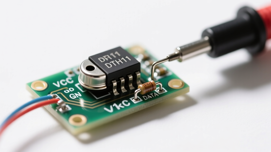
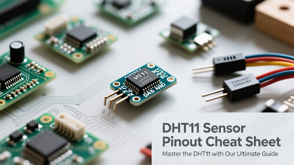
The DHT11 is commonly sold in two physical form factors: the bare 4-pin blue plastic package and a 3-pin or 4-pin PCB module. Understanding the difference is critical to avoid short circuits or floating data lines.
Bare 4-Pin Component Pinout
When looking at the bare sensor with the grill facing you, the pins from left to right are:
- Pin 1 (VDD): Power supply (3.3V - 5.5V).
- Pin 2 (DATA): Serial data output. Crucial: Requires an external 4.7kΩ to 10kΩ pull-up resistor to VDD.
- Pin 3 (NC): No Connect. Leave this pin floating; do not solder or wire it to ground.
- Pin 4 (GND): Ground connection.
PCB Module Variations
If you purchase a pre-soldered module (often mounted on a small board with three headers), the internal circuit already includes the necessary pull-up resistor and a 100nF decoupling capacitor. The pinout simplifies to:
- VCC / + : Connect to 3.3V or 5V.
- DATA / OUT : Connect to your microcontroller's digital GPIO pin.
- GND / - : Connect to system ground.
For comprehensive wiring diagrams and library integrations, the Adafruit DHT Guide remains the gold standard for Arduino and CircuitPython implementations.
Communication Protocol & Timing Cheat Sheet
Unlike I2C or SPI sensors, the DHT11 uses a proprietary single-wire (One-Wire) protocol. The microcontroller must 'bit-bang' the GPIO pin with microsecond precision to initiate a reading and parse the 40-bit data stream.
The 40-Bit Data Structure
Every successful read returns 40 bits (5 bytes) of data:
| Byte | Content | Example Value |
|---|---|---|
| Byte 1 | Humidity Integral | 55 (55%) |
| Byte 2 | Humidity Decimal | 0 (DHT11 always outputs 0 here) |
| Byte 3 | Temperature Integral | 24 (24°C) |
| Byte 4 | Temperature Decimal | 0 (DHT11 always outputs 0 here) |
| Byte 5 | Checksum | 79 (Sum of Bytes 1-4) |
Note: The checksum is calculated by adding the first four bytes and keeping the lowest 8 bits (e.g., Checksum = (Byte1 + Byte2 + Byte3 + Byte4) & 0xFF).
Timing Sequence Breakdown
To trigger a measurement, your microcontroller must execute the following timing sequence:
- Start Signal: MCU pulls the DATA line LOW for at least 18 milliseconds, then pulls HIGH for 20-40 microseconds.
- Sensor Response: The DHT11 detects the start signal and pulls the line LOW for 80 microseconds, then HIGH for 80 microseconds.
- Bit Transmission: The sensor sends 40 bits. Each bit begins with a 50-microsecond LOW voltage. The length of the subsequent HIGH voltage dictates the bit value:
- 26-28 microseconds HIGH = Logic '0'
- 70 microseconds HIGH = Logic '1'
For reliable parsing without blocking your main loop, utilize optimized libraries like the Adafruit DHT Sensor Library, which handles the interrupt-driven timing requirements natively.
DHT11 vs. DHT22 vs. AHT20: Component Selection Matrix
Is the DHT11 the right tool for your 2026 project? While cheap, its limitations often force engineers to upgrade. Use this matrix to select the correct sensor for your BOM (Bill of Materials).
| Feature | DHT11 | DHT22 (AM2302) | AHT20 (Modern I2C) |
|---|---|---|---|
| Protocol | Single-Wire (Bit-bang) | Single-Wire (Bit-bang) | I2C (Hardware Interrupt) |
| Temp Range | 0°C to 50°C | -40°C to 80°C | -40°C to 85°C |
| Temp Accuracy | ±2.0°C | ±0.5°C | ±0.3°C |
| Humidity Range | 20% to 80% RH | 0% to 100% RH | 0% to 100% RH |
| Sampling Rate | 1 Hz | 0.5 Hz (2-second intervals) | Fast (I2C bus speed dependent) |
| Average Cost | $1.00 - $1.50 | $4.00 - $6.00 | $1.50 - $2.50 |
| Best Use Case | Basic indoor room monitoring, STEM education. | Outdoor weather stations, greenhouse monitoring. | High-precision IoT nodes, battery-operated ESP32 deep-sleep applications. |
Troubleshooting Matrix: Common DHT11 Failure Modes
When your serial monitor spits out NaN (Not a Number) or timeout errors, consult this diagnostic matrix before blaming a defective sensor.
| Error Symptom | Probable Root Cause | Hardware / Software Fix |
|---|---|---|
| Checksum Mismatch | Electrical noise on the data line corrupting the final bits of the 40-bit stream. | Add a 0.1µF ceramic decoupling capacitor across VCC and GND. Ensure wire length is under 20m. |
| Timeout Error (No Response) | Missing pull-up resistor on the bare 4-pin component, or dead GPIO pin. | Solder a 4.7kΩ resistor between DATA and VCC. Verify GPIO isn't shared with an onboard LED (e.g., Pin 13 on Uno). |
| NaN Readings | Polling the sensor faster than the 1Hz maximum sampling rate. | Increase the delay() or non-blocking timer interval to at least 2000ms between reads. |
| Stuck at 0% Humidity | Sensor has been exposed to prolonged condensation or water submersion. | Power off and let the sensor dry in a low-humidity environment for 24 hours. Replace if the capacitive dielectric is permanently shorted. |
Pro-Tips for Long-Term Reliability
To ensure your DHT11 temperature humidity sensor survives outside the breadboard phase, implement these hardware-level safeguards:
- Dust and Debris: The blue plastic cap has micro-perforations. If deploying in dusty environments (like woodworking shops or 3D printer enclosures), wrap the sensor in a breathable PTFE (Teflon) membrane to prevent particulate clogging while allowing vapor transmission.
- Heat Isolation: Do not mount the DHT11 directly above voltage regulators, motor drivers, or ESP32 Wi-Fi antennas. The localized heat will artificially inflate your temperature readings and skew the relative humidity calculation downward.
- Deep Sleep Optimization: If using an ESP8266 or ESP32 in deep sleep, power the DHT11 from a dedicated GPIO pin rather than the constant 3.3V rail. Drive the GPIO HIGH only when waking up to take a reading, then drive it LOW before returning to sleep. This eliminates the sensor's 0.5mA standby current drain, vastly extending LiPo battery life.
For further reading on integrating environmental sensors into advanced microcontroller ecosystems, review the official DHT11 Technical Data Sheet for exact timing tolerances and internal schematic details.