
The Anatomy of a Failed Connector Solder Joint
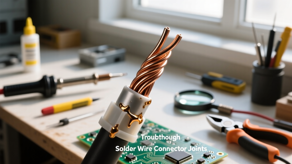
Soldering a wire to a connector seems like a fundamental skill, yet it remains one of the most common points of failure in DIY electronics, automotive wiring, and industrial harnesses. Unlike through-hole PCB soldering, connector joints are subjected to severe mechanical stress, thermal cycling, and vibration. When you are trying to figure out how to solder a wire to a connector properly, you must first understand why previous attempts failed.
A defective solder joint on a crimp or solder-cup connector doesn't just cause intermittent electrical contact; it can lead to catastrophic thermal runaway, short circuits, or complete harness failure under load. According to the IPC-A-610 Acceptability of Electronic Assemblies standard, a wire-to-connector joint must exhibit proper wetting, a smooth concave fillet, and no evidence of thermal damage to the insulating housing. When these criteria aren't met, troubleshooting must begin immediately.
Diagnostic Matrix: Identifying Your Soldering Failure
Before applying heat to salvage a bad connection, you must diagnose the specific failure mode. Use the following diagnostic matrix to identify what went wrong during your initial soldering attempt.
| Visual Symptom | Root Cause Analysis | Corrective Action Strategy |
|---|---|---|
| Plastic housing is warped, melted, or discolored | Excessive iron temperature, wrong tip geometry, or prolonged dwell time. | Reduce temp to 320°C, switch to a chisel tip, use thermal heatsink clips. |
| Solder creeps under the wire insulation | Wire stripped too far; capillary action (wicking) drew flux and solder up the strands. | Cut wire, re-strip to exact cup depth + 0.5mm, pre-tin carefully. |
| Solder balls up or looks dull and grainy | Cold joint due to oxidation inside the solder cup or insufficient flux activation. | Mechanically clean the cup, apply external ROL0 flux, pre-heat the cup. |
| Wire pulls out with minimal force | Lack of mechanical anchoring; solder acted as glue rather than a metallurgical bond. | Ensure wire is fully seated in the cup before solder flows. |
Failure Mode 1: Melted Plastic Housings (Thermal Runaway)
This is the most frequent disaster when working with high-density connectors like JST-XH (2.54mm pitch) or Molex Mini-Fit Jr. (4.2mm pitch). The plastic housings are typically made of Nylon 66 or PBT, which have relatively low melting points compared to the 350°C+ required to melt SAC305 lead-free solder.
The Troubleshooting Fix: Never use a fine conical tip for connector solder cups. Conical tips have poor thermal mass transfer, forcing the operator to hold the iron against the cup for 4 to 5 seconds, which conducts heat directly into the plastic. Instead, use a D24 Chisel tip or a C3 Bevel tip. These tips maximize surface area contact, transferring the necessary thermal energy in under 1.5 seconds. Furthermore, clamp an aluminum hemostat or specialized IC heatsink clip onto the wire between the solder cup and the plastic housing to absorb excess thermal energy.
Failure Mode 2: Solder Wicking and Brittle Strands
Solder wicking occurs when molten solder travels up the stranded wire beneath the insulation via capillary action. This creates a rigid, brittle section of wire right at the flex point. Under vibration, this stiffened section will snap, causing an open circuit. As noted in the SparkFun Guide to Through-Hole Soldering, managing flux and heat gradients is critical to preventing wicking.
The Troubleshooting Fix: The root cause is almost always over-stripping the wire. The exposed copper should never exceed the depth of the solder cup plus 0.5mm. If wicking has already occurred, you cannot simply melt it and push it back. You must use flush cutters to snip off the wick-hardened section, strip the wire correctly, and start over. Always tin the wire before inserting it into the cup, but use a minimal amount of solder to prevent the overall diameter from exceeding the cup opening.
Failure Mode 3: The "Cold" Barrel Joint
A cold joint in a D-Sub solder cup or a heavy-duty automotive barrel connector looks dull, frosty, and forms a convex blob rather than a smooth concave fillet. This happens because the heavy copper mass of the connector acts as a massive heatsink, dropping the localized temperature below the solder's liquidus point before the metallurgical bond can form.
The Troubleshooting Fix: Relying solely on the rosin core inside your solder wire is insufficient for heavy connector cups. You must introduce external flux. Apply a small drop of high-quality No-Clean or ROL0 liquid flux (such as Amtech or Chip Quik) directly into the empty solder cup. Next, touch your iron to the outside of the cup to pre-heat the mass. Only then should you feed the solder into the cup, followed by the pre-tinned wire.
Step-by-Step Recovery: How to Solder a Wire to a Connector Correctly
Once you have diagnosed the failure and prepared your workstation, follow this strict recovery protocol to ensure an IPC Class 2 compliant joint.
- Desolder and Clean: Use a desoldering braid (Solder Wick) coated with fresh flux to completely empty the connector cup. Do not leave old, oxidized solder residue inside.
- Mechanical Abrasion: If the inside of the cup is tarnished, use a fiberglass scratch pen to gently burnish the interior copper until it shines. Wipe away fiberglass debris with isopropyl alcohol (IPA).
- Precision Stripping: Strip the wire to the exact depth of the cup. Twist the strands tightly to prevent fraying.
- Pre-Tinning the Wire: Apply the iron to the wire and feed a microscopic amount of solder. The goal is to bind the strands together, not to create a thick coating.
- Flux the Cup: Apply a pin-drop of external liquid flux into the clean solder cup.
- The Mating Phase: Place your chisel tip against the side of the cup. Feed solder into the cup until it is 75% full. Remove the solder, then immediately insert the pre-tinned wire into the molten pool. Hold perfectly still for 2 seconds while the joint solidifies.
Expert Insight: Never apply the soldering iron directly to the wire while it is inside the plastic housing. The iron should only touch the metal terminal cup. Heating the wire directly will cause the insulation to melt back and expose bare copper, violating safety clearances.
Thermal Management Profiles by Connector Type
Different connectors require vastly different thermal strategies. Use this reference chart to configure your soldering station (e.g., Hakko FX-888D or Weller WE1010) before beginning your troubleshooting repair.
| Connector Family | Recommended Iron Temp (Leaded Sn60/Pb40) | Recommended Iron Temp (Lead-Free SAC305) | Optimal Tip Geometry | Max Dwell Time |
|---|---|---|---|---|
| JST-XH / PH (Small Pitch) | 310°C - 320°C | 340°C - 350°C | Micro Chisel (D12) or Knife (K) | 1.5 Seconds |
| Molex Mini-Fit Jr. | 330°C - 340°C | 350°C - 360°C | Standard Chisel (D24) | 2.0 Seconds |
| D-Sub Solder Cups | 350°C - 360°C | 370°C - 380°C | Large Bevel (C4) or Hoof | 3.0 Seconds |
| Heavy Duty Ring Terminals | 380°C+ | 400°C+ | Massive Chisel or specialized crimp-solder | 4.0 Seconds |
Expert Verification: Testing the Mechanical Bond
Visual inspection is only the first step in verifying your repair. The NASA Electronic Parts and Packaging (NEPP) Program emphasizes that mechanical integrity is just as vital as electrical continuity in high-reliability environments.
Perform the Tug Test: Grasp the wire approximately one inch from the connector and pull firmly in a straight line. A properly soldered joint will not yield; the wire strands should break before the solder joint fails. Next, use a digital multimeter in continuity mode to verify zero-resistance flow. Finally, inspect the joint under a 10x magnification loupe. You are looking for a smooth, shiny, concave fillet that smoothly transitions from the wire to the cup walls, with no evidence of flux carbonization or micro-cracking. By treating connector soldering as a precise metallurgical process rather than a simple craft, you eliminate the vast majority of field failures and harness callbacks.