
The Ubiquity of the 1uF Capacitor in Modern Electronics
Whether you are designing a high-speed digital PCB, repairing a vintage audio amplifier, or prototyping a microcontroller circuit, the 1 microfarad (1uF) capacitor is an indispensable component. It serves as the backbone for decoupling, noise filtering, and timing applications. However, for electronics hobbyists and technicians, identifying and verifying these components can be a source of frustration. Unlike resistors with their standardized color bands, capacitors rely on a fragmented system of alphanumeric markings. Understanding the 1 uF capacitor code is the first step toward accurate testing, measurement, and troubleshooting.
In this comprehensive testing and measurement guide, we will decode the ubiquitous '105' marking, explore how different dielectric materials handle the 1uF value, and detail the precise LCR and DMM measurement protocols required to verify component health in the lab.
Decoding the 1 uF Capacitor Code: The Math Behind '105'
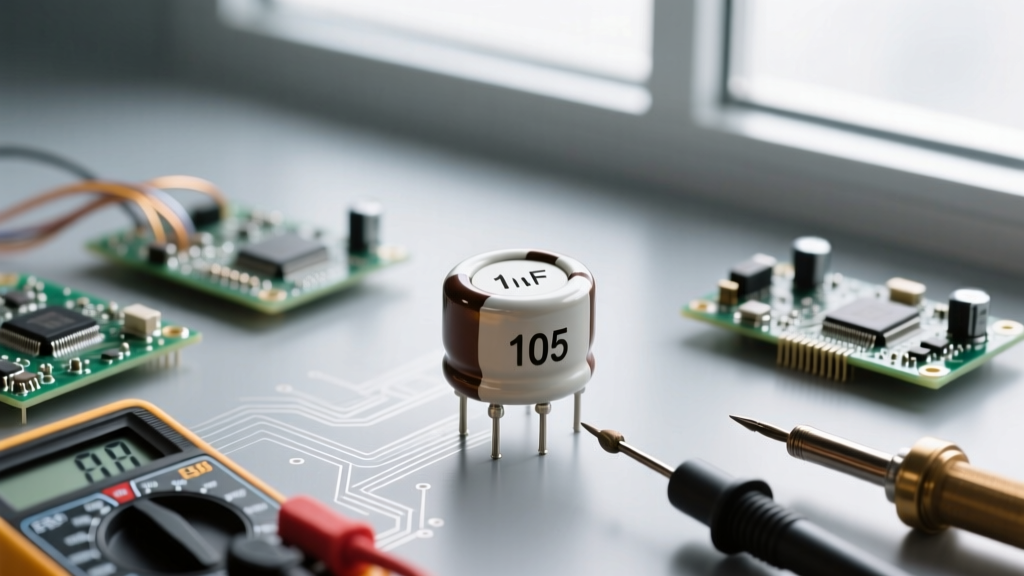
The most common surface-mount and through-hole ceramic or film capacitors use a three-digit EIA (Electronic Industries Alliance) code to denote capacitance in picofarads (pF). To understand why the 1 uF capacitor code is typically 105, we must break down the mathematical translation between picofarads, nanofarads, and microfarads.
- Base Unit: 1 Microfarad (µF) = 1,000 Nanofarads (nF) = 1,000,000 Picofarads (pF).
- First Two Digits (Significant Figures): The '10' represents the base number.
- Third Digit (Multiplier): The '5' represents the number of zeros to add to the base number (10^5).
Therefore, 10 followed by five zeros equals 1,000,000 pF. According to standard conversion, 1,000,000 pF is exactly 1uF. For an authoritative breakdown of these conversions, the All About Circuits Capacitor Calculator is an excellent bench-side reference tool.
Tolerance Letters Accompanying the Code
You will rarely see just '105' on a quality component. It is usually followed by a letter indicating the manufacturing tolerance. When testing, knowing this tolerance dictates whether a measured value is considered 'in spec' or degraded.
- J: ±5% (Common in precision film and C0G/NP0 ceramics)
- K: ±10% (Standard for X7R and X5R MLCCs)
- M: ±20% (Typical for high-capacitance dielectrics like Y5V or electrolytics)
- Z: +80% / -20% (Often found in cheap, unbranded decoupling capacitors)
Dielectric Variations: How 1uF is Marked Across Types
While '105' is the universal EIA code for 1uF, the physical marking changes drastically depending on the dielectric material and package type. As a test engineer, you must identify the dielectric before selecting the correct measurement frequency on your LCR meter.
| Dielectric Type | Typical 1uF Marking | Voltage Rating Example | Common Package / Form Factor |
|---|---|---|---|
| MLCC (Ceramic X7R/X5R) | 105K | 16V, 50V | SMD 0805, 0603, 1206 |
| Tantalum (Solid) | 105 (or Letter 'A' + 105) | 10V, 16V | SMD A, B, C case sizes |
| Aluminum Electrolytic | 1.0µF or 1R0 | 50V, 63V | Radial Through-Hole (4x7mm) |
| Polyester Film (Mylar) | 105J | 63V, 100V, 250V | Through-hole dipped or boxed |
For a deeper dive into the physical construction and dielectric behaviors of these components, SparkFun's Capacitor Tutorial provides excellent visual references for identifying unmarked or partially obscured SMD components.
Testing & Measurement Protocols for 1uF Capacitors
Measuring a 1uF capacitor requires more than simply touching multimeter probes to the leads. The measurement methodology must adapt to the component's dielectric properties and its intended application in the circuit.
Step 1: DMM Capacitance Measurement (Out-of-Circuit)
A common mistake in troubleshooting is attempting to measure capacitance in-circuit. A 1uF capacitor is frequently used in parallel decoupling networks alongside 0.1uF and 10uF capacitors. If you measure in-circuit, your Digital Multimeter (DMM) will sum the parallel capacitance, yielding a wildly inaccurate reading. Always desolder at least one leg of a through-hole component, or remove SMD components entirely, before testing capacitance.
Furthermore, ensure the capacitor is fully discharged before applying DMM probes. A charged 1uF capacitor at 50V can easily blow the internal protection fuse of your multimeter's capacitance measurement circuit.
Step 2: LCR Meter Calibration and Frequency Selection
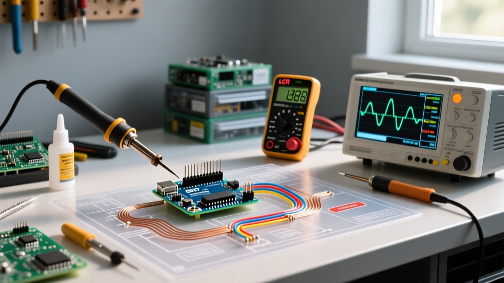
For professional validation, an LCR meter is mandatory. However, the test frequency must match the dielectric type:
- MLCC (Ceramic 105) & Film: Set the LCR meter to 1 kHz (or 1 MHz for RF applications). Use the Series (Cs) equivalent circuit model, as the Equivalent Series Resistance (ESR) of ceramics is extremely low (often < 0.05Ω).
- Aluminum Electrolytic (1.0µF): Set the LCR meter to 120 Hz. Electrolytics are typically used for low-frequency bulk filtering, and their capacitance drops significantly at higher frequencies. Use the Parallel (Cp) model to account for higher leakage currents.
Step 3: ESR and Leakage Current Profiling
In high-speed digital circuits, a 1uF ceramic capacitor's primary job is to supply instantaneous transient current. Therefore, its ESR is more critical than its exact capacitance. A 105 MLCC with an ESR exceeding 0.5Ω is likely suffering from internal delamination or micro-cracking and should be rejected. For 1uF tantalum capacitors, an ESR between 1.0Ω and 3.0Ω is normal, but any reading below 0.5Ω indicates a dendrite short is forming.
Real-World Failure Modes & Diagnostic Signatures
When a circuit fails, the 1uF capacitor is often the culprit. Recognizing the failure signatures specific to the '105' dielectrics will drastically reduce your diagnostic time.
MLCC Flex Cracking (Piezoelectric & Mechanical)
Multilayer Ceramic Capacitors (MLCCs) are brittle. If a PCB undergoes mechanical stress (e.g., board bending during connector insertion or thermal expansion mismatches), the ceramic body can develop micro-fractures. Diagnostic Signature: The LCR meter reads an 'Open' (OL) or erratic, fluctuating capacitance. Alternatively, a fracture that bridges internal electrodes will manifest as a dead short (0Ω resistance). Visual inspection under a microscope often reveals a hairline crack near the solder fillet.
Tantalum Thermal Runaway and Polarity Reversal
1uF tantalum capacitors are notorious for failing short-circuit. Unlike aluminum electrolytics, tantalums cannot tolerate even brief reverse voltage spikes (as low as 0.5V). Furthermore, they suffer from thermal runaway if subjected to high ripple currents. Diagnostic Signature: The component measures as a dead short on a DMM continuity test. Physically, the component may appear discolored, bulged, or, in catastrophic cases, cracked open with a burnt manganese dioxide smell.
Electrolytic Electrolyte Evaporation
Though less common in the 1uF value (as designers usually prefer ceramics for 1uF), small radial aluminum electrolytics are still found in vintage audio coupling circuits. Over decades, the liquid electrolyte evaporates through the rubber bung seal. Diagnostic Signature: Capacitance measures severely low (e.g., 0.2uF instead of 1.0uF), and the Dissipation Factor (D) or ESR spikes dramatically. According to Wikipedia's comprehensive guide on Electrolytic Capacitors, this drying out process accelerates exponentially when the component is located near heat sinks or power transistors.
Pro-Tip for Audio Restorers: When replacing 1uF electrolytic coupling capacitors in vintage amplifiers, never substitute them with standard X7R ceramics. X7R ceramics exhibit severe microphonic effects and voltage-dependent capacitance drop (DC bias effect), which will introduce harsh, non-linear distortion into the audio signal path. Always use WIMA film capacitors or C0G/NP0 ceramics for 1uF audio coupling.
Summary: Building a Reliable Testing Workflow
Mastering the 1 uF capacitor code goes far beyond memorizing that '105' equals one microfarad. True expertise in testing and measurement requires understanding the underlying dielectric physics, selecting the correct LCR meter parameters, and recognizing the unique failure modes of ceramics, tantalums, and electrolytics. By implementing out-of-circuit testing, matching test frequencies to component types, and profiling ESR alongside capacitance, you can confidently validate components and ensure the long-term reliability of your electronic designs.