
Opening Your Kit: The 3-Legged Mystery Component
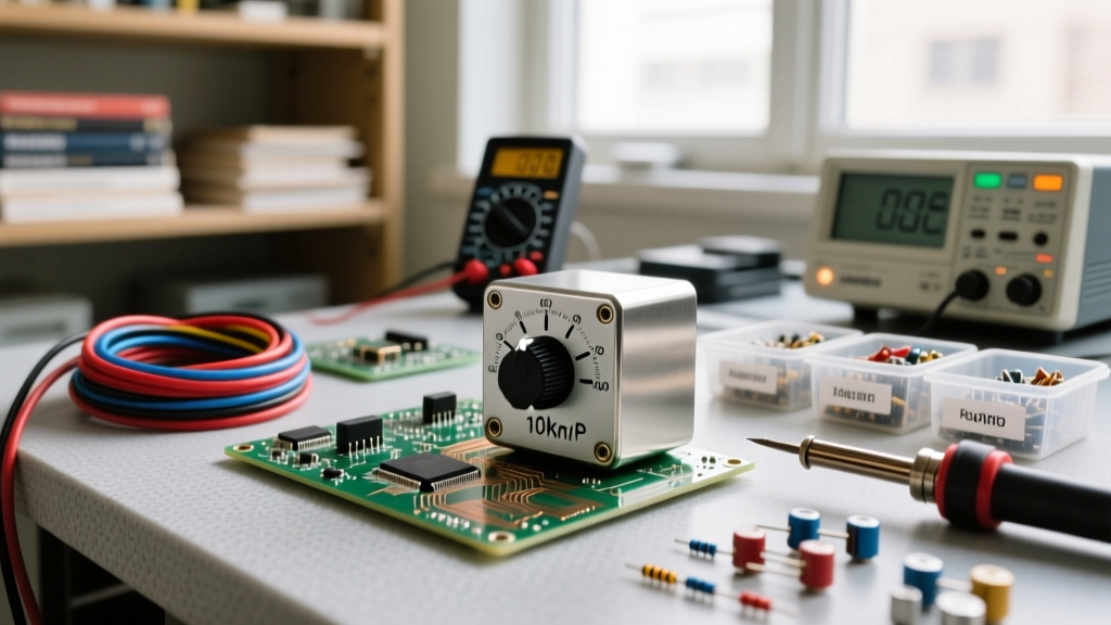
When you first unbox a beginner electronics kit—whether it is an Elegoo Super Starter Kit, a Rexqualis bundle, or a generic Arduino Uno pack—you will inevitably find a small, blue or black dial with three metal legs protruding from the bottom. This is the potentiometer, often affectionately called a 'pot.' While it looks simple, translating the physical component in your hand to a potentiometer diagram on a schematic can be a major stumbling block for newcomers.
Unlike a standard fixed resistor, which has two legs and a single schematic symbol, a potentiometer is a three-terminal device. It functions as a variable voltage divider or a variable resistor (rheostat). To use it correctly in your microcontroller projects, you must understand how the schematic diagram maps to the physical pins on your breadboard. This guide will decode the potentiometer diagram, explain the internal anatomy, and provide exact wiring frameworks for your first analog sensor projects.
Internal Anatomy: What the Diagram Represents
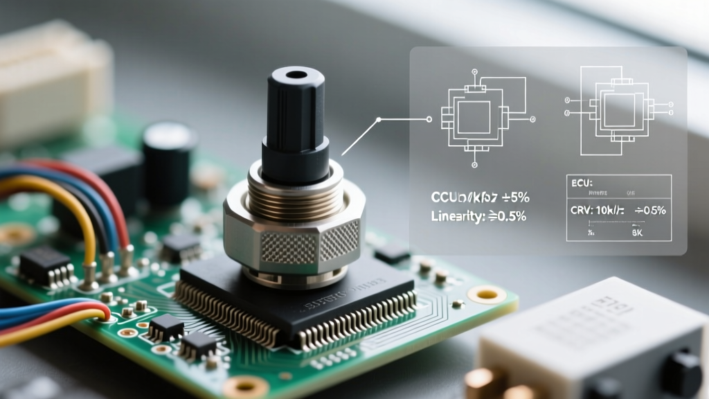
Before reading a schematic, you need to visualize what is happening inside the plastic housing. A standard carbon-track potentiometer (like the ubiquitous B10K found in almost every beginner kit) consists of two main internal components:
- The Resistive Element: A curved track made of carbon composition, cermet, or conductive plastic. The two ends of this track connect to the outer pins.
- The Wiper: A spring-loaded metal contact that rides along the resistive track as you turn the shaft. The wiper connects to the center pin.
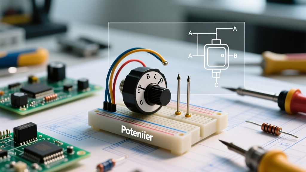
When you look at a potentiometer diagram, the schematic symbol is a direct abstraction of this physical reality. The resistive track is drawn as a resistor symbol, and the wiper is drawn as an arrow pointing at the track. Understanding this mechanical relationship is the key to mastering analog circuit design.
Decoding Schematic Symbols: US vs. IEC Standards
One of the most confusing aspects for beginners is encountering different schematic symbols for the exact same component. Depending on where you source your schematics, you will see one of two standards:
The US Standard (Zig-Zag)
In North American schematics, the resistive track is drawn using a zig-zag line. The arrow (wiper) points directly into the middle of the zig-zag. This is the most common symbol you will see in Arduino tutorials and hobbyist blogs.
The IEC Standard (Rectangle)
In international and professional engineering schematics, the resistive track is drawn as an empty rectangle. The wiper arrow points at the side of the rectangle. According to Electronics Tutorials, the IEC standard is preferred in modern CAD software like KiCad and Altium, so you will frequently encounter it if you download open-source hardware files from GitHub.
Pinout Mapping: Translating Diagram to Breadboard
The most critical step in using a potentiometer is mapping the schematic nodes to the physical pins. If you hold a standard B10K potentiometer with the shaft pointing toward you and the three pins pointing down, the pins are numbered from left to right.
| Physical Pin | Schematic Node | Internal Connection | Standard Breadboard Wiring (Voltage Divider) |
|---|---|---|---|
| Pin 1 (Left) | Terminal A (CCW) | Start of Carbon Track | Connect to Ground (GND) |
| Pin 2 (Center) | Wiper (Arrow) | Movable Contact | Connect to Analog Input (e.g., A0) |
| Pin 3 (Right) | Terminal B (CW) | End of Carbon Track | Connect to 5V or 3.3V (VCC) |
Note: Pin 1 and Pin 3 are electrically symmetrical regarding the total resistance. Swapping them will not damage the component, but it will reverse the direction of the dial's operation (e.g., turning clockwise will decrease the value instead of increasing it).
Wiring Frameworks: Two Ways to Use a Potentiometer
A potentiometer diagram usually implies one of two circuit configurations. As a beginner, you must decide which configuration your project requires before placing the component on the breadboard.
Configuration 1: The Voltage Divider (Potentiometer Mode)
This is the most common use case in microcontroller kits. You are using all three pins to create an adjustable voltage output. By connecting the outer pins to VCC and GND, the wiper outputs a voltage proportional to its physical position.
The math governing this is simple. As detailed in SparkFun's Voltage Divider tutorial, the output voltage (Vout) at the wiper is calculated as:
Vout = Vin × (R2 / (R1 + R2))
Where R1 is the resistance between VCC and the wiper, and R2 is the resistance between the wiper and GND.
When the dial is at 50%, the wiper reads exactly 2.5V (assuming a 5V input). This is perfect for reading analog inputs on an Arduino, where the Analog-to-Digital Converter (ADC) maps 0-5V to integer values between 0 and 1023.
Configuration 2: The Variable Resistor (Rheostat Mode)
Sometimes, a schematic diagram will show a potentiometer with only two terminals connected. This is a rheostat configuration, used to vary current rather than voltage. You might use this to manually dim an LED or adjust the gain on an op-amp.
Wiring Rule: Connect one outer pin (Pin 1 or 3) to the circuit, and connect the center Wiper pin (Pin 2) to the circuit. Leave the third outer pin completely disconnected. Pro-Tip: Many engineers tie the unused outer pin directly to the wiper pin. This ensures that if the wiper loses contact due to dirt or vibration, the circuit defaults to maximum resistance rather than breaking the connection entirely.
Understanding Taper: The Hidden Variable in Diagrams
A standard potentiometer diagram rarely specifies the 'taper'—the mathematical curve of the resistance change relative to the shaft rotation. In your beginner kit, you likely have a B10K potentiometer. The 'B' denotes a Linear Taper. If you turn the knob 50% of the way, the resistance is exactly 50% (5,000 ohms).
However, if you buy replacement parts for audio projects, you might encounter an A10K (Logarithmic/Audio Taper). Human hearing perceives volume logarithmically, so an audio pot stays at a low resistance for the first half of the turn, then ramps up sharply. If you mistakenly use an A-taper pot for an Arduino joystick or voltage divider project, your sensor readings will feel heavily skewed and non-linear. Always check the alphanumeric code printed on the back of the metal casing.
Real-World Troubleshooting: When the Diagram Fails You
Schematics represent ideal components. In reality, the physical potentiometers in beginner kits are cheap, mass-produced carbon-track devices prone to specific failure modes. Here is how to troubleshoot common issues when your breadboard build does not match the diagram's promise.
Issue 1: ADC Jitter and Noisy Readings
Symptom: You wire the voltage divider correctly, but the Arduino Serial Monitor shows the analog reading jumping erratically (e.g., 510, 514, 508, 515) even when you are not touching the dial.
The Cause: The carbon track has microscopic imperfections, and the Arduino's ADC is highly sensitive to high-impedance noise.
The Fix: Solder or breadboard a 0.1µF ceramic capacitor between the Wiper (Pin 2) and Ground. This creates a low-pass RC filter that smooths out the electrical noise, giving you a rock-solid reading.
Issue 2: The 'Scratchy' Dead Zone
Symptom: The dial works fine on the left and right extremes, but in the middle, the output drops to zero or behaves erratically.
The Cause: Oxidation or dust on the carbon track. This is incredibly common in cheap kit components that have been sitting in a warehouse for years.
The Fix: While replacement is the best long-term solution, you can temporarily fix this by injecting a tiny drop of contact cleaner (like DeoxIT) into the small slot on the back of the pot, then rotating the shaft back and forth 50 times to clean the wiper contact.
Summary for Your Next Build
Mastering the potentiometer diagram is a rite of passage for electronics hobbyists. By recognizing the difference between the US and IEC symbols, correctly mapping the three physical pins to the schematic nodes, and understanding the voltage divider math, you unlock the ability to build user interfaces, analog sensors, and adjustable power supplies. The next time you see that 3-legged blue dial in your kit, you will know exactly how to translate it from a schematic drawing to a functioning breadboard circuit.