
Demystifying the Variable Resistor in Your Kit
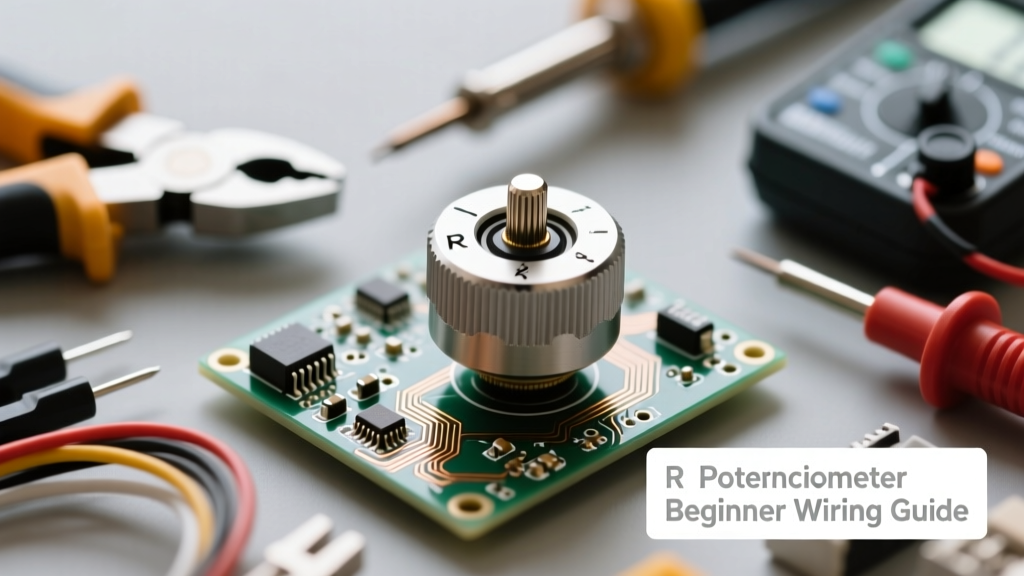
When you open your first electronics beginner component kit, you will inevitably find a small, three-terminal dial with a knurled plastic or metal shaft. In many schematic diagrams and older engineering notes, you will see this component referred to as an r potentiometer—a shorthand denoting a variable rotary resistor. While modern digital encoders have taken over high-end audio and industrial equipment, the analog potentiometer remains an absolute cornerstone for prototyping, sensor simulation, and user-input controls.
For a beginner, the r potentiometer is the perfect bridge between the physical and digital worlds. It allows you to translate a physical twisting motion into a variable voltage, which a microcontroller can then read via an Analog-to-Digital Converter (ADC). However, simply plugging it into a breadboard often leads to confusing readings, jittery outputs, and burned-out tracks. In this deep-dive guide, we will explore the internal anatomy, global taper standards, and professional wiring techniques required to master this component.
Anatomy of a Rotary Component
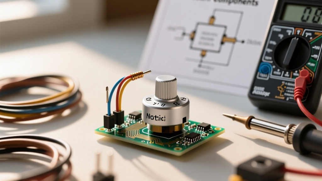
At its core, a standard rotary r potentiometer consists of a resistive element—usually a carbon composition track, a cermet (ceramic-metal) layer, or a conductive plastic ring—and a mechanical wiper. The three terminals on the bottom of the casing serve distinct purposes:
- Terminal 1 (CCW): The counter-clockwise end of the resistive track.
- Terminal 2 (Wiper): The middle pin, physically connected to the rotating shaft. This is your output signal.
- Terminal 3 (CW): The clockwise end of the resistive track.
The Crucial Difference: Potentiometer vs. Rheostat
A common beginner mistake is wiring the component as a rheostat when a voltage divider is needed. If you only use Terminal 2 and Terminal 3 (leaving Terminal 1 floating), you are using the component as a variable resistor (rheostat) to limit current. While this works for dimming a simple LED, it is entirely wrong for microcontroller inputs. To interface with an Arduino or ESP32, you must use all three terminals to create a voltage divider circuit, providing a stable, proportional voltage output to the ADC pin.
Decoding Taper Types: A, B, and C Markings
If you look closely at the metal casing of an r potentiometer, you will see a resistance value (e.g., 10K) followed by a letter, such as B10K or A10K. This letter indicates the 'taper'—the mathematical curve of the resistance change relative to the shaft rotation.
- Linear Taper (B): The resistance changes at a constant rate. At 50% physical rotation, the wiper sits at exactly 50% of the total resistance. This is the mandatory choice for microcontroller ADC inputs, as the microcontroller expects a linear voltage translation.
- Audio/Logarithmic Taper (A): The resistance changes slowly at first, then rapidly. This mimics the logarithmic way human ears perceive volume, making it ideal for analog audio amplifiers.
- Reverse Logarithmic (C): The opposite of the audio taper, rarely used but found in specific equalizer circuits.
The Global Naming Confusion
Here is a critical piece of E-E-A-T knowledge that trips up many hobbyists ordering parts online: Asian and Western taper codes are often reversed. In the US and Europe, 'A' means Logarithmic and 'B' means Linear. However, in many Asian-manufactured components (which populate 90% of cheap beginner kits), 'A' means Linear and 'B' means Logarithmic. Always verify the taper by measuring the resistance at the 50% rotation mark with a multimeter before soldering it to your PCB.
Step-by-Step Breadboard Wiring for Microcontrollers
To safely read an r potentiometer with a 5V Arduino Uno or a 3.3V ESP32, follow this exact wiring sequence:
- Connect Terminal 1 to Ground (GND).
- Connect Terminal 3 to your microcontroller's logic voltage (5V or 3.3V). Warning: Never feed 5V into an ESP32 ADC pin; use 3.3V.
- Connect Terminal 2 (Wiper) to an analog input pin (e.g., A0 on Arduino).
When you call the analogRead() function, the microcontroller measures the voltage at the wiper. Because the total resistance (e.g., 10,000 ohms) remains constant between VCC and GND, the current draw is minimal (0.5mA at 5V), protecting your board's power regulator while providing a smooth 0-1023 digital value.
Component Selection: Bourns vs. Alpha vs. Generic
Not all potentiometers are created equal. The generic, unbranded blue cylinders found in $10 Amazon kits suffer from severe contact bounce and carbon track degradation. If you are moving from breadboard to a permanent soldered project, invest in quality components.
| Brand / Model | Track Material | Rotational Torque | Lifespan (Cycles) | Best Use Case |
|---|---|---|---|---|
| Generic Kit (Blue) | Carbon Composition | Low / Inconsistent | ~5,000 | Temporary breadboarding |
| Alpha RD901F | Carbon / Cermet | Medium (Smooth) | ~15,000 | DIY Audio, Guitar Pedals |
| Bourns PTV09A | Carbon with Detents | High (Tactile Clicks) | ~30,000 | Industrial UI, Menu Navigation |
| TT Electronics P231 | Conductive Plastic | Very Smooth | ~100,000+ | High-precision lab equipment |
Common Prototyping Pitfalls and Noise Troubleshooting
The most frequent complaint from beginners is 'ADC jitter'—where the serial monitor shows the value bouncing between 510 and 515 even when the user isn't touching the shaft. This happens because the internal wiper of an r potentiometer acts like a tiny microphone, picking up electromagnetic interference (EMI) and suffering from microscopic contact bounce on the carbon track.
The Capacitor Filter Trick for ADC Jitter
To solve this hardware-level noise, you must implement a passive low-pass RC filter. Solder a 100nF (0.1µF) ceramic capacitor directly between the Wiper (Terminal 2) and Ground.
Pro-Tip: The capacitor acts as a tiny rechargeable battery that absorbs high-frequency voltage spikes caused by wiper bounce. Combined with the 10K resistance of the potentiometer, this creates a hardware low-pass filter that physically smooths the analog signal before it ever reaches the microcontroller's ADC pin, resulting in rock-solid readings.
Practical Project Ideas for Your First Build
Once you have mastered the wiring and noise filtering of the r potentiometer, try these foundational projects to build your prototyping muscle memory:
- Manual PWM LED Dimmer: Map the 0-1023 analog input to a 0-255 PWM output to smoothly fade a high-power LED without flickering.
- Servo Motor Position Controller: Use the linear voltage output to dictate the exact angle (0-180 degrees) of a micro-servo, perfect for building robotic arms or automated camera pans.
- Threshold Alarm System: Use the potentiometer to set a 'tripwire' threshold value in your code, allowing you to manually calibrate a photoresistor or temperature sensor alarm on the fly without re-uploading code.
By understanding the physical limitations, taper codes, and filtering requirements of the r potentiometer, you elevate your builds from frustrating, jittery prototypes to reliable, responsive electronic devices.