
The 2026 Reality of Component Sourcing and Verification
As we navigate the highly complex global supply chain in 2026, sourcing parts directly from authorized distributors remains the gold standard for mission-critical designs. However, prototyping labs, repair facilities, and mid-volume production houses frequently encounter components from a vast array of electronic component manufacturers through secondary markets, surplus brokers, and legacy inventory. The rise of AI-driven supply chain routing has inadvertently increased the prevalence of "ghost lots"—components manufactured to initial specifications but diverted before final QA testing or environmental screening.
Testing and measuring components is no longer just about verifying basic functionality; it is about authenticating the silicon, validating the passivation layers, and ensuring the part meets the rigorous datasheets published by top-tier manufacturers. This guide provides a deep-dive testing and measurement framework to verify components, spot sophisticated counterfeits, and ensure your circuit designs perform reliably under real-world stress.
Decoding the Landscape of Electronic Component Manufacturers
Before applying test probes to a lead frame, it is crucial to understand the manufacturing tiers. Different tiers exhibit distinct failure modes and require tailored testing approaches. Below is a breakdown of the manufacturer landscape and what to look for during electrical verification.
| Manufacturer Tier | Examples | Datasheet Accuracy | Common Failure Modes & Testing Focus |
|---|---|---|---|
| Tier 1 (Premium) | Texas Instruments, Analog Devices, Murata, STMicroelectronics | Extremely High (Includes min/max/typ over full temp range) | Counterfeit remarking, recycled die. Focus on thermal limits and quiescent current. |
| Tier 2 (Value/High-Volume) | Diodes Inc, Nexperia, Vishay, ON Semi | High (Focus on typical and max limits) | Lot variance, parametric drift. Focus on ESR, leakage current, and switching times. |
| Tier 3 / Clone | Various Shenzhen-based fabs, unbranded generic parts | Low (Often copied from Tier 1 datasheets without validation) | Catastrophic thermal failure, hFE collapse, severe MLCC DC bias droop. |
The Testing & Measurement Arsenal
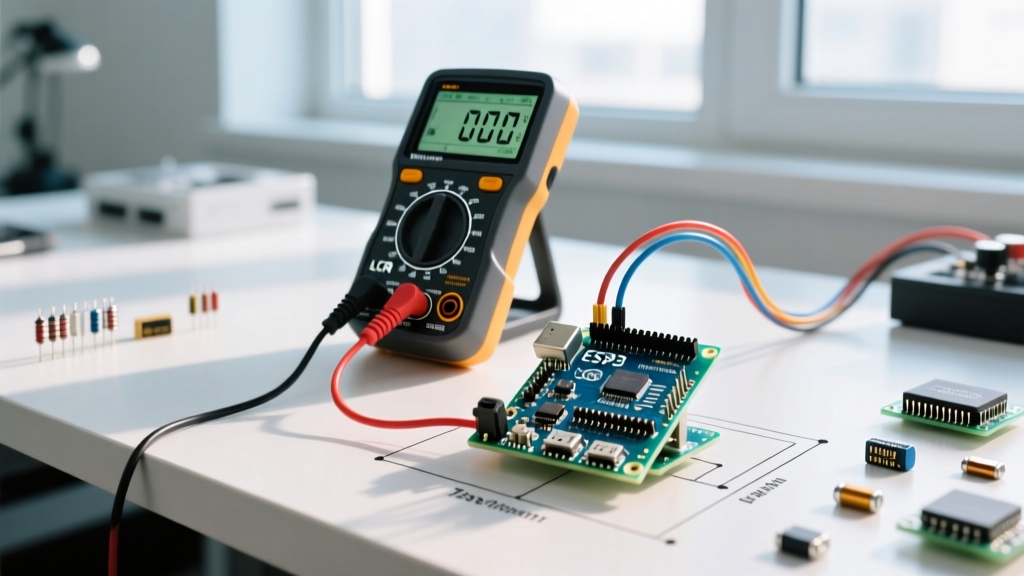
To effectively verify parts from various electronic component manufacturers, your lab bench requires more than a basic digital multimeter. Here are the critical instruments needed for deep verification in 2026.
1. Precision LCR Metering for Passive Components
When testing multilayer ceramic capacitors (MLCCs) from manufacturers like Murata or TDK, a standard capacitance reading at 1 kHz is virtually useless. Modern high-density X5R and X7R MLCCs suffer from severe capacitance droop under DC bias. A 10µF 0805 MLCC might measure perfectly at 0V but drop to 1.5µF at 50% of its rated voltage.
Actionable Setup: Use a benchtop LCR meter with a DC bias sweep capability, such as the Keysight E4980A (approx. $15,500) or the more budget-friendly Siglent ST5320 (approx. $1,800). Program a sweep from 0V to the component's rated voltage while measuring capacitance and Dissipation Factor (D). If the capacitance curve does not match the manufacturer's published DC bias graph, you are likely dealing with a lower-grade clone or a degraded, moisture-compromised part.
2. Curve Tracing for Active Semiconductors
Digital multimeters with diode-test functions cannot reveal the nuanced behavior of bipolar junction transistors (BJTs) or MOSFETs. To verify active parts from manufacturers like ON Semi or Infineon, a curve tracer is mandatory.
By sweeping the base current and measuring collector-emitter voltage, you can plot the hFE (current gain) across varying collector currents. Clone BJTs often exhibit an hFE that artificially peaks and then collapses at high currents due to inferior epitaxial layer doping. Furthermore, curve tracing reveals early thermal runaway tendencies that a static DMM test will completely miss.
3. Thermal Imaging and Power Cycling
Many counterfeit linear regulators and power management ICs are manufactured on smaller, cheaper die sizes that lack adequate thermal mass. Using a high-resolution thermal camera (like the FLIR T540) paired with an electronic load allows you to monitor the silicon junction temperature in real-time. By pushing the component to its datasheet-specified thermal shutdown threshold, you can verify if the internal protection circuitry actually exists or if the clone manufacturer simply omitted it to save mask costs.
Step-by-Step Authenticity Verification Workflow
When auditing a batch of components from an unfamiliar supplier, follow this strict "Trust but Verify" protocol. This methodology aligns with guidelines published by the NASA Electronic Parts and Packaging (NEPP) program, which sets the benchmark for aerospace-grade component authentication.
- Visual & Dimensional Inspection: Use a calibrated digital micrometer and a 100x stereomicroscope. Check lead width, package thickness, and pin coplanarity against the manufacturer's mechanical drawing. Counterfeiters often sand down the top of a package to remove old markings, reducing the overall thickness by 0.1mm to 0.3mm.
- Solvent Resistance Test: Vigorously swab the top marking with an acetone-soaked cotton swab for 30 seconds. Genuine laser-etched or epoxy-ink markings from Tier-1 manufacturers will not degrade. If the blacktop coating smears or the text fades, the part has been "blacktopped" and remarked.
- Electrical Baseline Testing: Measure quiescent current (Iq) and logic thresholds. Clones frequently draw 3x to 5x more standby current due to inferior CMOS process nodes.
- Decapsulation (Destructive): For high-value or safety-critical batches, use fuming nitric acid or automated laser decapsulation to expose the die. Compare the die layout, bond wire count, and manufacturer logo stamp against known-good reference databases.
Industry Standard Compliance: When establishing a testing lab for commercial production, ensure your inspection workflows comply with SAE AS5553 (Counterfeit Electronic Parts; Assuring Acquisition of Authentic and Conforming Parts) and IPC-1782. These standards provide the legal and operational frameworks for handling, testing, and quarantining suspect components. For detailed standard outlines, refer to the SAE International standards catalog and the IPC standards overview.
Real-World Case Study: The "Phantom" LM317 Voltage Regulator
To illustrate the importance of rigorous testing, consider a recent 2026 lab analysis of the ubiquitous LM317T adjustable linear regulator. A batch was sourced claiming to be manufactured by Texas Instruments. While the laser markings looked pristine and the package dimensions were within a 0.05mm tolerance, electrical testing revealed a different story.
Test 1: Quiescent Current (Iq)
The genuine TI LM317 datasheet specifies a typical quiescent current of 3.5 mA, with a maximum of 10 mA. When placed in a test jig with no load on the output, the suspect batch drew an average of 42 mA. This massive discrepancy indicated the internal bandgap reference and error amplifier were built on an outdated, leaky bipolar process node, likely a clone die from the early 2000s repackaged to look modern.
Test 2: Thermal Shutdown Threshold
The datasheet guarantees thermal shutdown at approximately 165°C. Using a thermocouple bonded directly to the copper tab and an electronic load drawing 1.5A, we intentionally induced thermal stress. The genuine TI part gracefully entered thermal limiting at 168°C, dropping the output voltage to protect the silicon. The suspect clone, lacking the integrated thermal shutdown transistor on the die, continued to conduct until the bond wires fused and the package vented toxic smoke at 210°C.
This case study proves that visual inspection is insufficient. Only by cross-referencing specific electrical parameters against the original electronic component manufacturers' datasheets can you guarantee circuit safety.
Best Practices for Prototyping and Production
Integrating a testing and measurement protocol into your workflow requires an upfront investment in time and equipment, but it prevents catastrophic field failures. Always maintain a "known-good" library of components sourced directly from authorized distributors like Digi-Key or Mouser. Use these golden samples to calibrate your LCR meters and curve tracers. When components arrive from secondary markets, never skip the DC bias sweeps for passives or the thermal stress tests for actives. By treating every component as guilty until proven innocent, you ensure your designs reflect the true performance intended by the world's leading electronic component manufacturers.