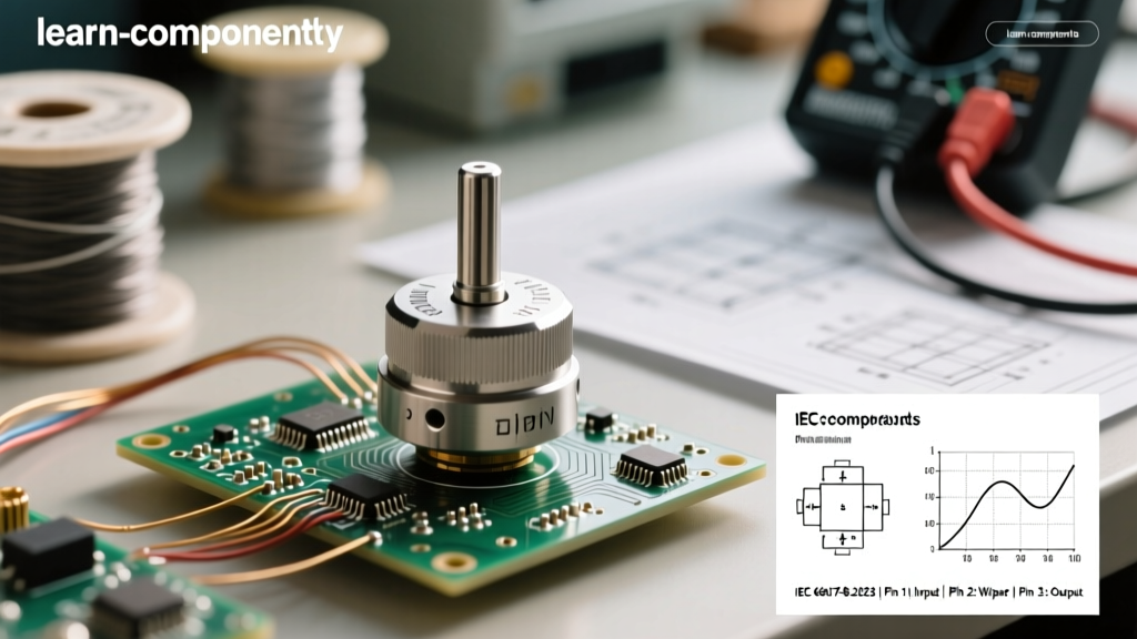

The Anatomy of a Potentiometer Schematic
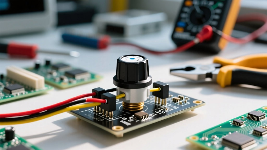
When designing a circuit or troubleshooting a PCB, interpreting the symbol potentiometer correctly is the bridge between a theoretical schematic and a functional physical prototype. Unlike fixed resistors, potentiometers (pots) introduce a third terminal—the wiper—adding mechanical and electrical complexity that must be meticulously detailed in manufacturer datasheets. Whether you are working with a massive wire-wound panel pot or a microscopic SMD cermet trimpot, the datasheet holds the key to understanding how the schematic symbol translates to real-world silicon and carbon tracks.
In this datasheet breakdown, we will dissect the standard schematic symbols, decode terminal designations, analyze taper curves, and explore the hidden electrical characteristics that separate a successful prototype from a noisy, failing circuit.
IEC vs. IEEE: Decoding the Schematic Symbol Potentiometer
The first hurdle in any datasheet or schematic review is recognizing which standard the design engineer followed. Globally, two primary standards dictate how a symbol potentiometer is drawn:
The IEEE Zig-Zag vs. The IEC Rectangle
According to SparkFun's schematic reading guide, the IEEE (Institute of Electrical and Electronics Engineers) standard, predominantly used in North America, represents a potentiometer as a zig-zag line (the resistor element) with an arrow pointing into the center (the wiper). Conversely, the IEC (International Electrotechnical Commission) standard, favored in Europe and Asia, represents the resistive element as a simple rectangular box, with the wiper depicted as an arrow crossing or pointing at the box.
Rheostat vs. Potentiometer Configurations
A critical detail often missed by beginners is how the symbol changes when a pot is wired as a rheostat (variable resistor) rather than a voltage divider. In a rheostat configuration, the wiper is tied directly to one of the end terminals. In a schematic, you will see the symbol potentiometer drawn with the wiper arrow looping back to connect to either the CW (Clockwise) or CCW (Counter-Clockwise) terminal. Datasheets will explicitly state the maximum power dissipation for rheostat wiring, which is often significantly lower than the total element rating due to localized heat concentration on a smaller segment of the resistive track.
Terminal Designations: CW, CCW, and the Wiper
One of the most frequent points of failure in DIY electronics is misinterpreting the pinout. A standard 3-pin potentiometer datasheet will label the terminals as follows:
- Terminal 1 (CCW): The counter-clockwise end of the resistive track. Typically tied to ground in a standard volume control voltage divider.
- Terminal 2 (Wiper): The variable output. This pin physically moves across the resistive element.
- Terminal 3 (CW): The clockwise end of the resistive track. Typically tied to VCC or the reference voltage.
Pro-Tip: Never assume Pin 1 is always the CCW terminal on physical components without checking the mechanical drawing in the datasheet. Manufacturers like ALPS and Bourns use specific physical reference tabs or asymmetric pin spacing to denote Pin 1, which correlates directly to the schematic symbol.
Reading the Taper Curve in the Datasheet
The schematic symbol only tells you what the component is; the taper curve tells you how it behaves. Page two of a comprehensive datasheet will almost always feature a graph plotting Mechanical Rotation (%) on the X-axis against Resistance Ratio (%) on the Y-axis.
The Regional Taper Code Trap
Datasheets use letter codes to denote the taper, but these codes are notoriously inconsistent across regions, leading to catastrophic ordering errors:
| Taper Code | IEC / Asian Standard | Older US Standard | Typical Application |
|---|---|---|---|
| B | Linear | Logarithmic (Audio) | Position sensors, LED dimming, balance controls |
| A | Logarithmic (Audio) | Linear | Audio volume controls (matches human hearing) |
| C | Anti-Logarithmic | Anti-Logarithmic | Specific temperature compensation circuits |
| W | W-Shape (Dual Audio) | N/A | Advanced audio mixing consoles |
Always verify the taper graph in the datasheet rather than relying solely on the 'A' or 'B' silkscreen marking on the component casing.
Hidden Electrical Characteristics: CRV and Resolution
When analyzing a high-quality Bourns 3296 Trimpot Datasheet, you will find parameters that are completely invisible in the schematic symbol but vital for precision analog design.
Contact Resistance Variation (CRV)
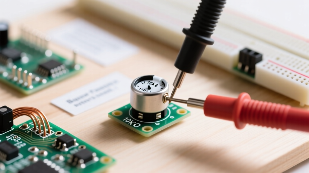
CRV measures the noise or resistance fluctuation generated between the wiper and the resistive track as the actuator is turned. In a cheap carbon-track pot, CRV might be specified as 3% or higher, which introduces audible 'scratch' noise in audio circuits or jitter in microcontroller ADC readings. Precision cermet or wire-wound pots will specify a CRV of 1% or a hard limit (e.g., ≤ 3Ω). If your schematic symbol is feeding a high-gain op-amp, ignoring the CRV spec will result in an unusable circuit.
Resolution and Independent Linearity
For wire-wound potentiometers, resolution is limited by the physical spacing of the wire coils. The datasheet will specify this as a percentage (e.g., 0.05%). Conductive plastic pots, however, offer 'infinite' resolution, making them the mandatory choice for high-fidelity servo feedback loops, even if their schematic symbol looks identical to a wire-wound pot.
Mechanical Drawings and Tolerance Stack-Up
The schematic symbol is a purely electrical abstraction. To actually route a PCB footprint, you must cross-reference the symbol with the mechanical drawing section of the datasheet. Pay close attention to:
- Actuator Type: Slotted (flathead), cross-recessed (Phillips), or top-adjust vs. side-adjust. This dictates your enclosure design and accessibility for field calibration.
- Wiper Pin Placement: On multi-turn trimpots (like the Bourns 3296W), the wiper pin is often physically located between the two end terminals on the PCB footprint, but on single-turn panel pots, the wiper may be the center pin physically, yet offset in the schematic layout for routing convenience.
- Rotational Torque: Specified in oz-in or N-cm. Crucial for robotics and motorized faders where a stepper motor must drive the potentiometer shaft without stalling.
Common Datasheet Pitfalls and Troubleshooting
Even experienced engineers make mistakes when translating the symbol potentiometer into physical reality. Here are three common pitfalls and how to resolve them:
- The 'Reverse Taper' Bug: You wired the pot according to the schematic, but turning the knob clockwise decreases the value. Fix: You likely swapped the CW and CCW terminals. Check the datasheet's mechanical drawing to see which physical pin corresponds to Terminal 1 (CCW) when viewing the pot from the bottom.
- ADC Jitter: Your microcontroller is reading erratic values from the wiper. Fix: You chose a pot with a high CRV or a resistance value too high for the ADC's sample-and-hold capacitor to charge properly. Add a 10nF to 100nF ceramic capacitor between the wiper and ground to create a low-pass filter.
- Thermal Drift: The calibration of your trimpot shifts as the enclosure heats up. Fix: Check the Temperature Coefficient (TC) in the datasheet. Carbon composition pots can have a TC of ±1000 ppm/°C. Upgrade to a cermet trimpot with a TC of ±100 ppm/°C for stable reference voltage generation.
Conclusion
The symbol potentiometer on your schematic is merely the tip of the iceberg. By diving deep into the manufacturer's datasheet—scrutinizing the IEC/IEEE symbol variations, verifying regional taper codes, and respecting the mechanical and CRV limits—you ensure that your physical prototype will perform exactly as your theoretical design intended. Always let the datasheet, not just the schematic symbol, guide your component selection and PCB layout.