
The Core Potentiometer Meaning in Circuit Design
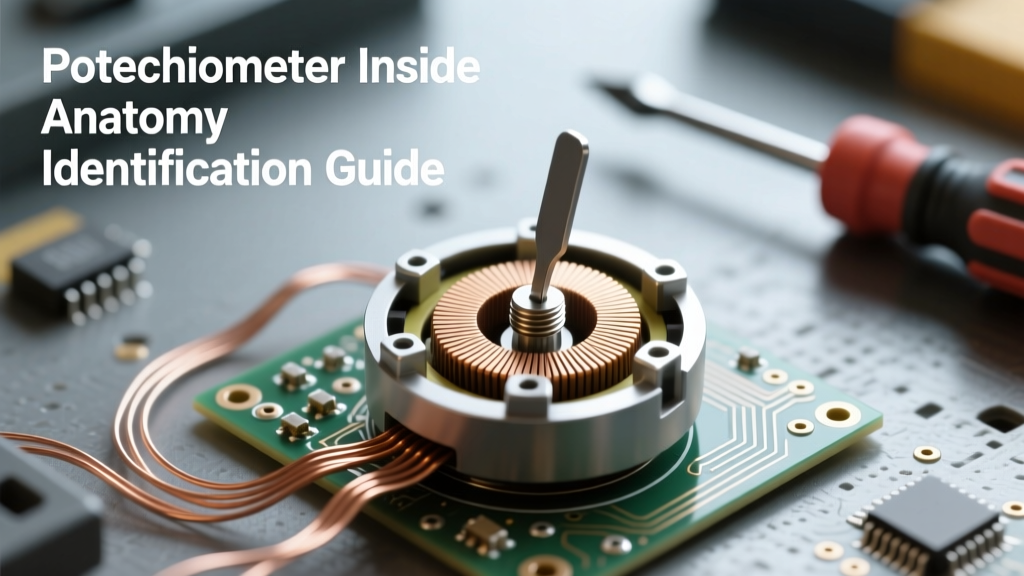
When beginners search for the potentiometer meaning, they are usually met with a basic dictionary definition: a three-terminal resistor featuring a sliding or rotating contact that forms an adjustable voltage divider. However, in professional electronics, PCB prototyping, and embedded systems design, the true engineering meaning of a potentiometer extends far beyond this rudimentary explanation.
In practical circuit design, a potentiometer is a transducer that converts mechanical displacement into a variable electrical resistance or voltage ratio. To truly understand how a potentiometer will behave in your analog signal path or power regulation circuit, you must look past the basic symbol and dive directly into the manufacturer's datasheet. This guide breaks down the critical parameters found in industry-standard potentiometer datasheets, using the ubiquitous Bourns 3296W Cermet Trimpot and ALPS carbon film audio potentiometers as our primary case studies.
Deconstructing the Datasheet: Bourns 3296W Cermet Trimpot
The Bourns 3296W-1-103LF (a 10kΩ multi-turn trimpot) is a staple in prototyping labs and production PCBs alike. Priced at approximately $1.50 to $2.20 on major distributors like DigiKey and Mouser, it offers a fascinating look into how manufacturers specify mechanical and electrical limits.
Electrical Characteristics and Thermal Derating
The most misunderstood parameter in any potentiometer datasheet is the power rating. The 3296W is rated for 0.5 Watts at 70°C. However, datasheets include a thermal derating curve that is critical for reliability. If your PCB operates in an enclosure that reaches 100°C, the allowable power dissipation drops to roughly 0.2 Watts. Exceeding this causes the resistive element to overheat, leading to permanent drift in the resistance value or catastrophic open-circuit failure.
Design Rule of Thumb: Never use a standard potentiometer as a high-current rheostat (two-terminal variable resistor) in power paths. The wiper contact is typically rated for milliamps, not amps. Using a 10kΩ pot to dim a 12V/2A LED strip will instantly vaporize the wiper trace.
Mechanical Limits: Rotational Torque and Cycle Life
Datasheets specify rotational torque to ensure compatibility with automated assembly or user-interface knobs. The Bourns 3296W specifies a starting torque of 280 gf·cm (gram-force centimeters) maximum, and a running torque of 200 gf·cm. More importantly, the mechanical cycle life is rated for 200 turns. This reveals the true meaning of a 'trimpot'—it is designed for 'set-and-forget' calibration during manufacturing, not for daily user adjustment. For user-facing dials, you must select a panel-mount pot rated for 100,000+ cycles.
Decoding the Taper: Linear, Audio, and Logarithmic
The 'taper' defines the mathematical relationship between the physical shaft rotation and the electrical resistance output. Misinterpreting the taper code on a datasheet is a frequent cause of poor UI design in audio and instrumentation projects.
- B-Taper (Linear): Resistance changes at a constant rate. A 50% physical rotation yields exactly 50% of the total resistance. Ideal for voltage dividers, sensor calibration, and op-amp feedback networks.
- A-Taper (Audio/Logarithmic): Resistance changes slowly at first, then rapidly. This mimics the human ear's logarithmic perception of loudness. A 50% rotation might yield only 15% of the total resistance.
- C-Taper (Reverse Logarithmic): The inverse of the A-taper, often used in specific analog synth filter cutoff circuits or specialized gain staging.
According to All About Circuits, assuming a linear taper when an audio taper is required will result in a volume knob that does 'nothing' for the first 70% of its rotation, and then blasts to maximum volume in the final 30%.
Material Technologies: Carbon, Cermet, and Conductive Plastic
The resistive track material fundamentally dictates the component's resolution, noise floor, and lifespan. Below is a structured comparison of the three dominant technologies found in modern datasheets.
| Material | Resolution | Typical Lifespan | Temperature Coefficient | Best Application |
|---|---|---|---|---|
| Carbon Film | Low (Granular) | 15,000 - 100,000 cycles | High (±1000 ppm/°C) | Audio volume controls, basic UI knobs |
| Cermet | Medium | 200 - 1,000 cycles | Low (±100 ppm/°C) | PCB calibration, bias trimming, set-and-forget |
| Conductive Plastic | Infinite (Smooth) | 5,000,000+ cycles | Very Low (±20 ppm/°C) | Servo feedback, joysticks, precision medical gear |
Real-World Failure Modes: CRV and Wiper Noise
When designing low-noise analog front-ends or high-gain audio preamps, the most critical datasheet parameters are CRV (Contact Resistance Variation) and ENR (Equivalent Noise Resistance).
CRV measures the maximum change in resistance between the wiper and the resistive track as the shaft is turned. In a cheap carbon film pot, microscopic pits and oxidation on the track cause the wiper to 'bounce' electrically, injecting severe crackling noise into an audio signal path. A high-quality conductive plastic potentiometer, such as the Bourns 665 series (which retails for upwards of $15.00), will specify a CRV of less than 1 ohm, ensuring dead-silent operation even in high-fidelity mixing consoles.
Furthermore, environmental factors like humidity and flux residue from PCB assembly can cause electrochemical migration across the resistive track. Bourns technical documentation heavily emphasizes the necessity of sealed potentiometers (often denoted by an IP67 rating or a specific 'sealed' sub-family) if the board will be exposed to harsh environments or require ultrasonic cleaning post-soldering.
Prototyping vs. Production Selection Framework
Understanding the potentiometer meaning in a commercial context requires balancing prototyping convenience with production viability. Use the following decision framework for your next PCB layout:
- Breadboarding Phase: Use standard 10kΩ linear (B-taper) through-hole carbon pots. They are cheap, forgiving, and easy to swap.
- Proof-of-Concept PCB: Transition to SMD Cermet trimpots (like the Bourns 3364 series) for internal calibration points. Ensure the footprint includes a silkscreen indicator for the wiper pin to avoid routing errors.
- User-Facing Interface: If the end-user will turn the knob daily, you must specify a panel-mount conductive plastic or high-grade carbon pot with a metal shaft and a minimum 50,000-cycle mechanical rating.
- High-Precision Feedback: For robotics or servo position feedback, abandon standard pots entirely in favor of Hall-effect rotary sensors or multi-turn conductive plastic pots to eliminate mechanical dead-bands.
Final Thoughts on Component Specification
The true potentiometer meaning is not just a variable resistor; it is a complex electromechanical transducer governed by strict thermal, mechanical, and material limits. By learning to read the derating curves, torque specifications, and CRV metrics in a datasheet, you elevate your prototyping from amateur guesswork to professional engineering. Always match the track material and taper to your specific signal domain, and never ignore the thermal limits of the wiper contact.