
The Anatomy of a Potentiometer: Lugs, Wipers, and Tracks
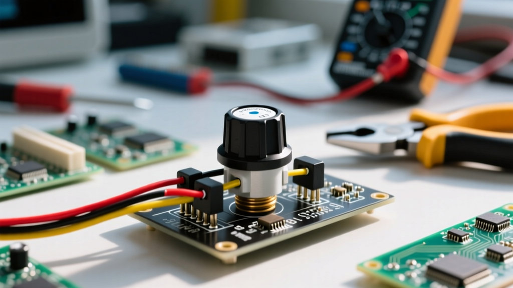
Before interpreting any potentiometer connection diagram, you must understand the physical architecture of the component. A standard 3-terminal potentiometer (often called a 'pot') consists of a resistive track—typically made of carbon composition, cermet, or conductive plastic—and a mechanical wiper that slides across this track. The three connection lugs serve distinct roles:
- Lug 1 (CCW): Connected to one end of the resistive track (usually the counter-clockwise extreme).
- Lug 2 (Wiper): The variable center tap connected to the mechanical slider.
- Lug 3 (CW): Connected to the opposite end of the resistive track (clockwise extreme).
While the resistive track provides a fixed total resistance (e.g., 10kΩ), the wiper allows you to tap into any fractional resistance point along that track. This fundamental mechanic is what allows a single component to act as either a voltage divider or a variable resistor, depending entirely on how you wire it into your circuit.
Identifying Pins on Unmarked Potentiometers
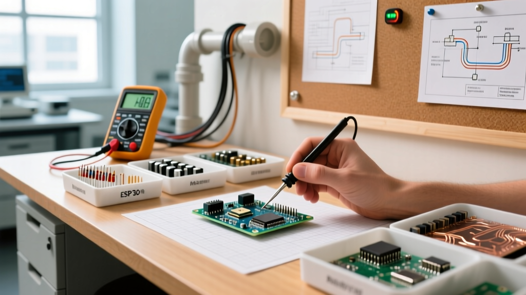
Not every potentiometer comes with a clear silkscreen or datasheet, especially when salvaging components or using generic overseas clones. Before consulting a schematic, use a digital multimeter (DMM) to map your specific pinout:
- Set your DMM to measure resistance (Ω) on an appropriate scale.
- Place your probes on Lug 1 and Lug 3. Rotate the shaft fully back and forth. The resistance reading should remain completely static and equal to the pot's rated value (e.g., 10kΩ). These are your outer track terminals.
- Move one probe to Lug 2 (the middle lug) while keeping the other on an outer lug. Rotate the shaft. The resistance should smoothly sweep from near 0Ω up to the maximum rated value. Lug 2 is confirmed as your wiper.
Decoding the Potentiometer Connection Diagram
There are two primary ways to wire a 3-terminal pot into a circuit. The correct potentiometer connection diagram depends entirely on whether you need to scale a voltage or limit current.
Configuration 1: The Voltage Divider (3-Terminal Wiring)
When you need to provide a variable reference voltage to an analog-to-digital converter (ADC), an op-amp input, or a bias network, you wire the potentiometer as a voltage divider. This requires all three lugs.
- Lug 1: Connect to VCC (e.g., 5V or 3.3V).
- Lug 3: Connect to Ground (GND).
- Lug 2 (Wiper): Connect to your microcontroller's ADC pin or op-amp input.
As you rotate the shaft, the wiper outputs a variable voltage between 0V and VCC. According to All About Circuits, the output voltage is calculated using the standard voltage divider formula:
Vout = Vin × (R2 / (R1 + R2))
Where R1 is the resistance between Lug 1 and the Wiper, and R2 is the resistance between the Wiper and Lug 3. Because the total resistance remains constant, the current drawn from the VCC rail remains constant, making this an incredibly stable configuration for sensor inputs and UI dials.
Configuration 2: The Variable Resistor / Rheostat (2-Terminal Wiring)
If your goal is to actively limit current—such as dimming an LED, controlling a motor's speed via a PWM base, or tuning an RC oscillator frequency—you only need to use the potentiometer as a variable resistor (rheostat). In this configuration, you technically only need two connections, but best practices dictate a specific three-lug approach.
- Lug 1: Connect to the circuit path.
- Lug 2 (Wiper): Connect to the load or the other side of the circuit path.
- Lug 3: Left electrically floating in basic diagrams, but must be tied to Lug 2 in professional designs.
Master Prototyper Tip: When wiring a potentiometer as a variable resistor, always solder a jumper wire between the wiper (Lug 2) and the unused terminal (Lug 3). If the wiper momentarily loses contact with the resistive track due to vibration, mechanical shock, or internal debris, the circuit will default to the maximum resistance value rather than creating an infinite open circuit. This prevents runaway signals and catastrophic failures in sensitive applications like motor speed controllers or audio amplifiers.
Taper Selection: Linear (B) vs. Audio (A) Wiring Implications
A connection diagram is only half the battle; you must also select the correct taper. The taper defines the mathematical relationship between the physical rotation of the shaft and the resistance output.
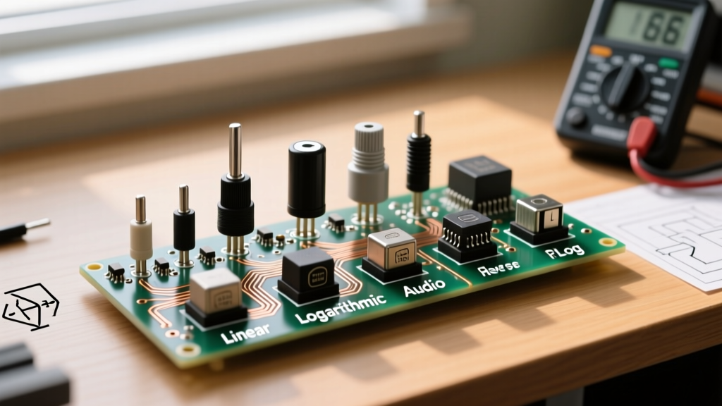
- Linear Taper (Marked 'B', e.g., B10K): The resistance changes at a constant rate. Rotating the shaft 50% yields exactly 50% of the total resistance. This is mandatory for voltage dividers, sensor calibration, and measurement equipment.
- Logarithmic / Audio Taper (Marked 'A', e.g., A10K): The resistance changes slowly at first, then rapidly. This mimics the logarithmic way human ears perceive volume. If you use an Audio taper pot in a linear voltage divider circuit for a microcontroller, your ADC readings will be heavily skewed and non-linear, ruining your calibration data.
Real-World Wiring Scenarios and Component Pinouts
The physical orientation of the lugs changes drastically depending on whether you are using a panel-mount potentiometer or a PCB-mount trimpot. Misinterpreting the viewing angle (top vs. bottom) is the #1 cause of reversed wiring in DIY electronics. Below is a comparison of two industry-standard models to illustrate these differences.
| Specification | Bourns 3296W (Trimpot) | Alpha RD901F (Panel Mount) |
|---|---|---|
| Application | PCB calibration, set-and-forget tuning | Audio mixers, user-facing UI dials |
| Track Material | Cermet (High temp stability) | Carbon Composition |
| Mechanical Rotation | 25-Turn (Multi-turn precision) | 300° (Single-turn) |
| Pinout Orientation | Viewed from TOP (component side) | Viewed from BOTTOM (solder side) |
| Standard Pin Order | Lug 1 (Left), Lug 2 (Center), Lug 3 (Right) | Lug 1 (Right), Lug 2 (Center), Lug 3 (Left) |
As noted in the Bourns 3296 series datasheet, viewing angles are critical. Always verify pin 1 with a multimeter before applying power, especially when transitioning between panel-mount and PCB-mount components in the same schematic.
Troubleshooting Common Potentiometer Wiring Failures
Even with a perfect potentiometer connection diagram, physical components introduce real-world parasitic effects and failure modes. Here is how to diagnose and fix the most common issues encountered on the prototyping bench:
1. Wiper Noise and 'Scratchy' Audio
In audio circuits or sensitive DC bias networks, rotating the pot may introduce a harsh scratching noise or erratic voltage spikes. This is caused by microscopic debris or oxidation on the carbon track interrupting the wiper's contact. The Fix: Do not replace the component immediately. Apply a specialized contact cleaner like DeoxIT D5 into the small casing slots and rotate the shaft 50 times to burnish the track clean.
2. Parasitic Inductance in Wirewound Pots
If you are using a high-power wirewound potentiometer for a high-frequency RF circuit or a fast-switching PWM load, the coiled wire inside the pot acts as an inductor. This parasitic inductance can cause voltage ringing and phase shifts. The Fix: Switch to a conductive plastic or cermet track potentiometer, which exhibits virtually zero parasitic inductance.
3. Ground Loop Hum in Audio Mixers
When wiring multiple panel-mount audio potentiometers, daisy-chaining the ground connections (Lug 3) from one pot casing to the next often creates a ground loop, resulting in a persistent 50/60Hz mains hum. The Fix: Use a star-grounding topology. Run an individual ground wire from Lug 3 of every single potentiometer directly to a single, centralized ground point on the main PCB or power supply filter capacitor.
Summary Checklist for Prototyping
Before finalizing your solder joints or ordering your custom PCB, run through this quick verification checklist:
- Did I verify the wiper pin with a multimeter rather than relying on visual assumptions?
- Is my taper (Linear 'B' vs Audio 'A') matched to the intended circuit function?
- If used as a rheostat, is the wiper tied to the unused outer lug to prevent open-circuit failures?
- Have I accounted for the viewing angle (top vs. bottom) in my PCB footprint design?
Mastering the nuances of the potentiometer connection diagram bridges the gap between a theoretical schematic and a robust, noise-free physical prototype. For further reading on integrating variable resistors with microcontrollers, check out the SparkFun Inventor's Kit guide on potentiometers to see how these analog signals are translated into digital actions.